1 案例:配置浮动路由
1.1 问题
- 配置接口IP地址
- 配置浮动路由,实现链路的冗余
- 验证浮动路由的效果
1.2 方案
使用eNSP搭建实验环境,如图-1所示。
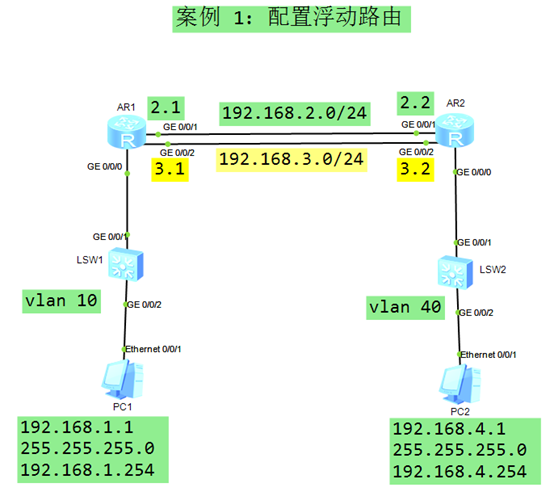 图-1
图-1
1.3 步骤
实现此案例需要按照如下步骤进行。
[hidecontent type=”payshow”]
配置终端设备 PC-1 和 PC-2
- PC-1 IP 地址:
- 192.168.1.1
- 255.255.255.0
- 192.168.1.254
- PC-2 IP 地址:
- 192.168.4.1
- 255.255.255.0
- 192.168.4.254
- <Huawei>system–view // 进入系统视图
- [Huawei]sysname SW1 // 修改设备名称为 SW1
- [SW1] vlan 10 // 创建 vlan 10
- [SW1–vlan10]quit
- [SW1]interface GigabitEthernet 0/0/1 // SW1 与 R1 的互联接口
- [SW1–GigabitEthernet0/0/1]port link–type access // 配置链路类型为 access
- [SW1–GigabitEthernet0/0/1]port default vlan 10 // 将端口加入 vlan 10
- [SW1–GigabitEthernet0/0/1]quit
- [SW1]interface gi0/0/2 // SW1 与 PC1 的互联接口
- [SW1–GigabitEthernet0/0/2]port link–type access // 配置链路类型为 access
- [SW1–GigabitEthernet0/0/2]port default vlan 10 // 将端口加入 vlan 10
- [SW1–GigabitEthernet0/0/2]quit
- <Huawei>system–view // 进入系统视图
- [Huawei]sysname SW2 // 修改设备名称为 SW2
- [SW2] vlan 40 // 创建 vlan 40
- [SW2–vlan40]quit
- [SW2]interface GigabitEthernet 0/0/1 // SW2 与 R2 的互联接口
- [SW2–GigabitEthernet0/0/1]port link–type access // 配置链路类型为 access
- [SW2–GigabitEthernet0/0/1]port default vlan 40 // 将端口加入 vlan 40
- [SW2–GigabitEthernet0/0/1]quit
- [SW2]interface gi0/0/2 // SW2 与 PC2 的互联接口
- [SW2–GigabitEthernet0/0/2]port link–type access // 配置链路类型为 access
- [SW2–GigabitEthernet0/0/2]port default vlan 40 // 将端口加入 vlan 40
- [SW2–GigabitEthernet0/0/2]quit
- <Huawei>system–view
- [Huawei]sysname R1
- [R1]interface GigabitEthernet 0/0/0 // PC-1的网关接口
- [R1–GigabitEthernet0/0/0]ip address 192.168.1.254 24
- [R1–GigabitEthernet0/0/0]quit
- [R1]interface GigabitEthernet 0/0/1 // R1-R2之间的主链路
- [R1–GigabitEthernet0/0/1]ip address 192.168.2.1 24
- [R1–GigabitEthernet0/0/1]quit
- [R1]interface GigabitEthernet 0/0/2 // R1-R2之间的备份链路
- [R1–GigabitEthernet0/0/2]ip address 192.168.3.1 24
- [R1–GigabitEthernet0/0/2]quit
- <Huawei>system–view
- [Huawei]sysname R2
- [R2]interface GigabitEthernet 0/0/0 // PC-2的网关接口
- [R2–GigabitEthernet0/0/0]ip address 192.168.4.254 24
- [R2–GigabitEthernet0/0/0]quit
- [R2]interface GigabitEthernet 0/0/1 // R2-R1之间的主链路
- [R2–GigabitEthernet0/0/1]ip address 192.168.2.2 24
- [R2–GigabitEthernet0/0/1]quit
- [R2]interface GigabitEthernet 0/0/2 // R2-R1之间的备份链路
- [R2–GigabitEthernet0/0/2]ip address 192.168.3.2 24
- [R2–GigabitEthernet0/0/2]quit
配置浮动静态路由 – R1
- [R1]ip route–static 192.168.4.0 255.255.255.0 192.168.2.2 // 主链路对应的路由
- [R1]ip route–static 192.168.4.0 255.255.255.0 192.168.3.2 preference 100
配置浮动静态路由 – R2
- [R2]ip route–static 192.168.1.0 255.255.255.0 192.168.2.1 // 主链路对应的路由
- [R2]ip route–static 192.168.1.0 255.255.255.0 192.168.3.1 preference 100
测试
- PC-1:
- Ping 192.168.4.1 –t // 一直向 192.168.4.1 发送 ping 包
- – 可以访问成功,R1使用的主链路对应的路由条目
- – 断开 R1 的 Gi0/0/1 接口,依然可以访问成功;使用的是备份链路对应
- 路由条目
2 案例:配置网关备份
2.1 问题
- 配置接口IP地址
- 如图配置 VRRP 虚拟网关 和 优先级
- 验证每个网关的状态
2.2 方案
搭建实验环境,如图-2所示。
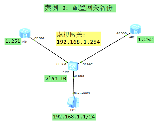 图-2
图-2
2.3 步骤
实现此案例需要按照如下步骤进行。
配置终端设备 PC1
- PC-1 IP 地址:
- 192.168.1.1
- 255.255.255.0
- 192.168.1.254 // 后期通过 VRRP 形成的 虚拟网关IP
配置 SW1
- <Huawei>system–view // 进入系统视图
- [Huawei]sysname SW1 // 修改设备名称为 SW1
- [SW1] vlan 10 // 创建 vlan 10
- [SW1–vlan10]quit
- [SW1]interface GigabitEthernet 0/0/1 // SW1 与 R1 的互联接口
- [SW1–GigabitEthernet0/0/1]port link–type access // 配置链路类型为 access
- [SW1–GigabitEthernet0/0/1]port default vlan 10 // 将端口加入 vlan 10
- [SW1–GigabitEthernet0/0/1]quit
- [SW1]interface gi0/0/2 // SW1 与 R2 的互联接口
- [SW1–GigabitEthernet0/0/2]port link–type access // 配置链路类型为 access
- [SW1–GigabitEthernet0/0/2]port default vlan 10 // 将端口加入 vlan 10
- [SW1–GigabitEthernet0/0/2]quit
- [SW1]interface gi0/0/3 // SW1 与 PC1 的互联接口
- [SW1–GigabitEthernet0/0/3]port link–type access // 配置链路类型为 access
- [SW1–GigabitEthernet0/0/3]port default vlan 10 // 将端口加入 vlan 10
- [SW1–GigabitEthernet0/0/3]quit
配置R1
- <Huawei>system–view
- [Huawei]sysname R1
- [R1]interface GigabitEthernet 0/0/0 // R1与SW1 的互联接口
- [R1–GigabitEthernet0/0/0]ip address 192.168.1.251 24
- [R1–GigabitEthernet0/0/0]quit
配置R2
- <Huawei>system–view
- [Huawei]sysname R2
- [R2]interface GigabitEthernet 0/0/0 // R2与SW1 的互联接口
- [R2–GigabitEthernet0/0/0]ip address 192.168.1.252 24
- [R2–GigabitEthernet0/0/0]quit
配置R1 的 VRRP
- [R1]interface GigabitEthernet 0/0/0
- [R1–GigabitEthernet0/0/0]vrrp vrid 1 virtual–ip 192.168.1.254 // 设置虚拟网关
- [R1–GigabitEthernet0/0/0]vrrp vrid 1 priority 200 // 设置 VRRP 优先级为 200
配置 R2 的 VRRP
- [R2]interface GigabitEthernet 0/0/0
- [R2–GigabitEthernet0/0/0]vrrp vrid 1 virtual–ip 192.168.1.254 // 设置虚拟网关
查看VRRP信息
- [R1]display vrrp brief // 查看 R1 在 VRRP 中的状态,是主(Master)网关
- Total:1 Master:1 Backup:0 Non–active:0
- VRID State Interface Type Virtual IP
- —————————————————————-
- 1 Master GE0/0/0 Normal 192.168.1.254
- [R2]display vrrp brief // 查看 R2 在 VRRP 中的状态,是备份(Backup)网关
- Total:1 Master:0 Backup:1 Non–active:0
- VRID State Interface Type Virtual IP
- —————————————————————-
- 1 Backup GE0/0/0 Normal 192.168.1.254
测试终端与网关的连通性
- PC-1:
- Ping 192.168.1.254 –t // PC1 访问自己的网关
- – 可以访问成功,数据包发向主网关 R1 (在R1上抓包可以验证)
- – 断开 R1 的 Gi0/0/0 接口,依然可以访问成功;数据包发向网关 R2
- – R1 的 Gi0/0/0 接口修复成功,数据包再次发向网关 R1
3 案例:VRRP 链路跟踪
3.1 问题
- 配置接口IP地址
- 配置 VRRP 主备网关
- 配置 VRRP 链路跟踪
- 断开 R1 Gi0/0/1 查看 VRRP 状态
- 打开 R1 Gi0/0/1 查看 VRRP 状态
3.2 方案
搭建实验环境,如图-3所示。
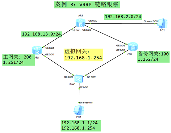 图-3
图-3
3.3 步骤
实现此案例需要按照如下步骤进行。
配置终端设备 PC1
- PC-1 IP 地址:
- 192.168.1.1
- 255.255.255.0
- 192.168.1.254 // 后期通过 VRRP 形成的 虚拟网关IP
- PC-2 IP 地址:
- 192.168.2.1
- 255.255.255.0
- 192.168.2.254 // R3的网关接口IP地址
配置 SW1
- <Huawei>system–view // 进入系统视图
- [Huawei]sysname SW1 // 修改设备名称为 SW1
- [SW1]interface GigabitEthernet 0/0/1 // SW1 与 R1 的互联接口
- [SW1–GigabitEthernet0/0/1]port link–type access // 配置链路类型为 access
- [SW1–GigabitEthernet0/0/1]quit
- [SW1]interface gi0/0/2 // SW1 与 R2 的互联接口
- [SW1–GigabitEthernet0/0/2]port link–type access // 配置链路类型为 access
- [SW1–GigabitEthernet0/0/2]quit
- [SW1]interface gi0/0/3 // SW1 与 PC1 的互联接口
- [SW1–GigabitEthernet0/0/3]port link–type access // 配置链路类型为 access
- [SW1–GigabitEthernet0/0/3]quit
配置R1
- <Huawei>system–view
- [Huawei]sysname R1
- [R1]interface GigabitEthernet 0/0/0 // R1与SW1 的互联接口
- [R1–GigabitEthernet0/0/0]ip address 192.168.1.251 24
- [R1–GigabitEthernet0/0/0]quit
- [R1]interface GigabitEthernet 0/0/1 // R1与R3 的互联接口
- [R1–GigabitEthernet0/0/1]ip address 192.168.13.1 24
- [R1–GigabitEthernet0/0/1]quit
- [R1]ip route–static 192.168.2.0 24 192.168.13.3 // 添加去往 PC2 的路由
配置R2
- <Huawei>system–view
- [Huawei]sysname R2
- [R2]interface GigabitEthernet 0/0/0 // R2与SW1 的互联接口
- [R2–GigabitEthernet0/0/0]ip address 192.168.1.252 24
- [R2–GigabitEthernet0/0/0]quit
- [R2]interface GigabitEthernet 0/0/2 // R2与R3 的互联接口
- [R2–GigabitEthernet0/0/2]ip address 192.168.23.2 24
- [R2–GigabitEthernet0/0/2]quit
- [R2]ip route–static 192.168.2.0 24 192.168.23.3 // 添加去往 PC2 的路由
配置R3
- <Huawei>system–view
- [Huawei]sysname R3
- [R3]interface GigabitEthernet 0/0/0 // R3与PC2 的互联接口
- [R3–GigabitEthernet0/0/0]ip address 192.168.2.254 24
- [R3–GigabitEthernet0/0/0]quit
- [R3]interface GigabitEthernet 0/0/1 // R3与R1 的互联接口
- [R3–GigabitEthernet0/0/1]ip address 192.168.13.3 24
- [R3–GigabitEthernet0/0/1]quit
- [R3]interface GigabitEthernet 0/0/2 // R3与R2 的互联接口
- [R3–GigabitEthernet0/0/2]ip address 192.168.23.3 24
- [R3–GigabitEthernet0/0/2]quit
- [R3]ip route–static 192.168.1.0 24 192.168.13.1 // 添加去往 PC1 的主路由
- [R3]ip route–static 192.168.1.0 24 192.168.23.2 preference 100
- // 添加去往 PC1 的备份路由
配置 R1 的 VRRP
- [R1]interface GigabitEthernet 0/0/0
- [R1–GigabitEthernet0/0/0]vrrp vrid 1 virtual–ip 192.168.1.254 // 设置虚拟网关
- [R1–GigabitEthernet0/0/0]vrrp vrid 1 priority 200 // 设置 VRRP 优先级为 200
配置 R2 的 VRRP
- [R2]interface GigabitEthernet 0/0/0
- [R2–GigabitEthernet0/0/0]vrrp vrid 1 virtual–ip 192.168.1.254 // 设置虚拟网关
配置 R1 的 VRRP 链路跟踪
- [R1]interface GigabitEthernet 0/0/0 // PC1 的网关接口
- [R1–GigabitEthernet0/0/0] vrrp vrid 1 track interface gi0/0/1 reduced 110
- // 接口Gi0/0/1 断开后,vrrp 优先级降低 110,变成90
测试 VRRP 链路跟踪,Gi0/0/1 断开之前
- [R1]display vrrp brief // 查看 R1 在 VRRP 中的状态,是主(Master)网关
- Total:1 Master:1 Backup:0 Non–active:0
- VRID State Interface Type Virtual IP
- —————————————————————-
- 1 Master GE0/0/0 Normal 192.168.1.254
- [R2]display vrrp brief // 查看 R2 在 VRRP 中的状态,是备份(Backup)网关
- Total:1 Master:0 Backup:1 Non–active:0
- VRID State Interface Type Virtual IP
- —————————————————————-
- 1 Backup GE0/0/0 Normal 192.168.1.254
测试 VRRP 链路跟踪,Gi0/0/1 断开之后
- [R1]interface GigabitEthernet 0/0/1
- [R1–GigabitEthernet0/0/1] shutdown // 关闭 VRRP 协议跟踪的端口 Gi0/0/1
- [R2]display vrrp brief // 查看 R2 在 VRRP 中的状态,是主(Master)网关
- Total:1 Master:1 Backup:0 Non–active:0
- VRID State Interface Type Virtual IP
- —————————————————————-
- 1 Master GE0/0/0 Normal 192.168.1.254
- [R1]display vrrp brief // 查看 R1 在 VRRP 中的状态,是备份(Backup)网关
- Total:1 Master:0 Backup:1 Non–active:0
- VRID State Interface Type Virtual IP
- —————————————————————-
- 1 Backup GE0/0/0 Normal 192.168.1.254
- [R1]display vrrp
- GigabitEthernet0/0/0 | Virtual Router 1
- State : Backup // R1 的 VRRP 状态为“备份”
- Virtual IP : 192.168.1.254 // 虚拟网关IP地址
- Master IP : 192.168.1.252 // 当前主网关设备的接口IP地址
- PriorityRun : 90 // 当前本设备运行的 VRRP 优先级为 90
- PriorityConfig : 200 // 当前本设备配置的 VRRP 优先级为 200
- MasterPriority : 100 // 当前主网关的 VRRP 优先级为 100
- Preempt : YES Delay Time : 0 s
- TimerRun : 1 s
- TimerConfig : 1 s
- Auth type : NONE
- Virtual MAC : 0000-5e00-0101
- Check TTL : YES
- Config type : normal–vrrp
- Backup–forward : disabled
- Track IF : GigabitEthernet0/0/1 Priority reduced : 110 // VRRP 链路跟踪配置
- IF state : DOWN // 被跟踪的接口处于 DOWN 的状态
- Create time : 2020-02-12 18:24:59 UTC-08:00
- Last change time : 2020-02-12 18:25:46 UTC-08:00
4 案例:VRRP安全认证
4.1 问题
- 如图配置设备的IP地址
- 在R1和R3之间建立BFD会话,快速检测链路故障
- 查看R1和R3之间的BFD会话状态的信息
4.2 方案
搭建实验环境,如图-4所示。
 图-4
图-4
4.3 步骤
实现此案例需要按照如下步骤进行。
配置R1
- Huawei>system–view
- [Huawei]sysname R1
- [R1]interface GigabitEthernet 0/0/0
- [R1–GigabitEthernet0/0/0]ip address 192.168.12.1 24
- [R1–GigabitEthernet0/0/0]quit
- [R1]ip route–static 192.168.23.0 24 192.168.12.2
配置R2
- <Huawei>system–view
- [Huawei]sysname R2
- [R2]interface GigabitEthernet 0/0/1
- [R2–GigabitEthernet0/0/1]ip address 192.168.12.2 24
- [R2–GigabitEthernet0/0/1]quit
- [R2]interface GigabitEthernet 0/0/0
- [R2–GigabitEthernet0/0/0]ip address 192.168.23.2 24
- [R2–GigabitEthernet0/0/0]quit
配置R3
- <Huawei>system–view
- [Huawei]sysname R3
- [R3]interface GigabitEthernet 0/0/1
- [R3–GigabitEthernet0/0/1]ip address 192.168.23.3 24
- [R3–GigabitEthernet0/0/1]quit
- [R3]ip route–static 192.168.12.0 24 192.168.23.2
配置BFD-R1
- [R1]bfd
- [R1–bfd]quit
- [R1]bfd 13 bind peer 192.168.23.3
- [R1–bfd–session-13]discriminator local 1
- [R1–bfd–session-13]discriminator remote 3
- [R1–bfd–session-13]commit
- [R1–bfd–session-13]quit
配置BFD-R3
- [R3]bfd
- [R3–bfd]quit
- [R3]bfd 13 bind peer 192.168.12.1
- [R3–bfd–session-13]discriminator local 3
- [R3–bfd–session-13]discriminator remote 1
- [R3–bfd–session-13]commit
- [R3–bfd–session-13]quit
验证 BFD 会话
- [R1]display bfd session all
- ——————————————————————————–
- Local Remote PeerIpAddr State Type InterfaceName
- ——————————————————————————–
- 1 3 192.168.23.3 Up S_IP_PEER –
- ——————————————————————————–
- Total UP/DOWN Session Number : 1/0
- [R3]display bfd session all
- ——————————————————————————–
- Local Remote PeerIpAddr State Type InterfaceName
- ——————————————————————————–
- 3 1 192.168.12.1 Up S_IP_PEER –
- ——————————————————————————–
- Total UP/DOWN Session Number : 1/0
5 案例:VRRP安全认证
5.1 问题
- 如图配置IP地址
- 如图配置 VRRP 网关角色
- 配置 VRRP 密文安全认证
- 配置 VRRP 认证密码为 Tarena
- 验证 VRRP 网关状态
5.2 方案
搭建实验环境,如图-5所示。
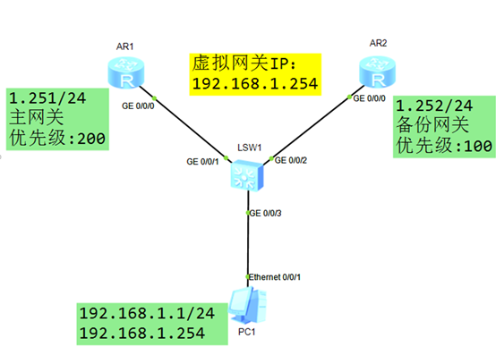 图-5
图-5
5.3 步骤
实现此案例需要按照如下步骤进行。
配置终端设备 PC1
- PC-1 IP 地址:
- 192.168.1.1
- 255.255.255.0
- 192.168.1.254 // 后期通过 VRRP 形成的 虚拟网关IP
配置 SW1
- <Huawei>system–view // 进入系统视图
- [Huawei]sysname SW1 // 修改设备名称为 SW1
- [SW1]interface GigabitEthernet 0/0/1 // SW1 与 R1 的互联接口
- [SW1–GigabitEthernet0/0/1]port link–type access // 配置链路类型为 access
- [SW1–GigabitEthernet0/0/1]quit
- [SW1]interface gi0/0/2 // SW1 与 R2 的互联接口
- [SW1–GigabitEthernet0/0/2]port link–type access // 配置链路类型为 access
- [SW1–GigabitEthernet0/0/2]quit
- [SW1]interface gi0/0/3 // SW1 与 PC1 的互联接口
- [SW1–GigabitEthernet0/0/3]port link–type access // 配置链路类型为 access
- [SW1–GigabitEthernet0/0/3]quit
配置R1
- <Huawei>system–view
- [Huawei]sysname R1
- [R1]interface GigabitEthernet 0/0/0 // R1与SW1 的互联接口
- [R1–GigabitEthernet0/0/0]ip address 192.168.1.251 24
- [R1–GigabitEthernet0/0/0]quit
配置R2
- <Huawei>system–view
- [Huawei]sysname R2
- [R2]interface GigabitEthernet 0/0/0 // R2与SW1 的互联接口
- [R2–GigabitEthernet0/0/0]ip address 192.168.1.252 24
- [R2–GigabitEthernet0/0/0]quit
配置R1 的 VRRP 和 MD5认证
- [R1]interface GigabitEthernet 0/0/0
- [R1–GigabitEthernet0/0/0]vrrp vrid 1 virtual–ip 192.168.1.254 // 设置虚拟网关
- [R1–GigabitEthernet0/0/0]vrrp vrid 1 priority 200 // 设置 VRRP 优先级为 200
- [R1–GigabitEthernet0/0/0]vrrp vrid 1 authentication–mode md5 Tarena //配置密码
配置 R2 的 VRRP 和 MD5认证
- [R2]interface GigabitEthernet 0/0/0
- [R2–GigabitEthernet0/0/0]vrrp vrid 1 virtual–ip 192.168.1.254 // 设置虚拟网关
- [R2–GigabitEthernet0/0/0]vrrp vrid 1 authentication–mode md5 Tarena //配置密码
查看VRRP信息
- [R1]display vrrp brief // 查看 R1 在 VRRP 中的状态,是主(Master)网关
- Total:1 Master:1 Backup:0 Non–active:0
- VRID State Interface Type Virtual IP
- —————————————————————-
- 1 Master GE0/0/0 Normal 192.168.1.254
- [R2]display vrrp brief // 查看 R2 在 VRRP 中的状态,是备份(Backup)网关
- Total:1 Master:0 Backup:1 Non–active:0
- VRID State Interface Type Virtual IP
- —————————————————————-
- 1 Backup GE0/0/0 Normal 192.168.1.254
验证 VRRP 的 认证信息
- [R1]display vrrp
- GigabitEthernet0/0/0 | Virtual Router 1
- State : Master
- Virtual IP : 192.168.1.254
- Master IP : 192.168.1.251
- PriorityRun : 200
- PriorityConfig : 200
- MasterPriority : 200
- Preempt : YES Delay Time : 0 s
- TimerRun : 1 s
- TimerConfig : 1 s
- Auth type : MD5 Auth key : %$%$xARSEjt8IF–Pl0703EiPd+`k%$%$ // 认证类型和密码
- Virtual MAC : 0000-5e00-0101
- Check TTL : YES
- Config type : normal–vrrp
- Backup–forward : disabled
- Create time : 2020-02-14 11:16:14 UTC-08:00
- Last change time : 2020-02-14 11:16:15 UTC-08:00
6 案例:多 VLAN 网关负载均衡
6.1 问题
- Vlan 6 的主网关在 SW1,优先级为 150
- Vlan 6 的备份网关在 SW2 ,优先级为 130
- Vlan 8 的主网关在 SW2 ,优先级为 150
- Vlan 8 的备份网关在 SW1 ,优先级为 130
- Vlan 6 的虚拟IP地址为:192.168.6.254
- Vlan 8 的虚拟IP 地址为:192.168.8.254
6.2 方案
搭建实验环境,如图-6所示。
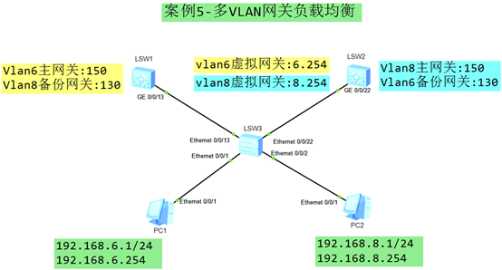 图-6
图-6
6.3 步骤
实现此案例需要按照如下步骤进行。
配置终端设备 PC1
- PC-1 IP 地址:
- 192.168.6.1
- 255.255.255.0
- 192.168.6.254 // 后期通过 VRRP 形成的 虚拟网关IP
- PC-2 IP 地址:
- 192.168.8.1
- 255.255.255.0
- 192.168.8.254 // 后期通过 VRRP 形成的 虚拟网关IP
配置 SW3
- <Huawei>system–view // 进入系统视图
- [Huawei]sysname SW3 // 修改设备名称为 SW3
- [SW3] vlan batch 6 8 // 批量创建 vlan 6 和 vlan 8
- [SW3]interface Ethernet0/0/1 // SW3 与 PC1 的互联接口
- [SW3–Ethernet0/0/1]port link–type access // 配置链路类型为 access
- [SW3–Ethernet0/0/1]port default vlan 6 // 将 接口加入到 vlan 6
- [SW3–Ethernet0/0/1]quit
- [SW3]interface Ethernet0/0/2 // SW3 与 PC2 的互联接口
- [SW3–Ethernet0/0/2]port link–type access // 配置链路类型为 access
- [SW3–Ethernet0/0/2]port default vlan 8 // 将 接口加入到 vlan 8
- [SW3–Ethernet0/0/2]quit
- [SW3]interface Ethernet0/0/13 // SW3 与 SW1 的互联接口
- [SW3–Ethernet0/0/13]port link–type trunk // 配置链路类型为 Trunk
- [SW3–Ethernet0/0/13]port trunk allow–pass vlan all // 设置 Trunk 允许所有 vlan
- [SW3–Ethernet0/0/13]quit
- [SW3]interface Ethernet0/0/22 // SW3 与 SW2 的互联接口
- [SW3–Ethernet0/0/22]port link–type trunk // 配置链路类型为 Trunk
- [SW3–Ethernet0/0/22]port trunk allow–pass vlan all // 设置 Trunk 允许所有 vlan
- [SW3–Ethernet0/0/22]quit
配置SW1
- <Huawei>system–view // 进入系统视图
- [Huawei]sysname SW1 // 修改设备名称为 SW1
- [SW1] vlan batch 6 8 // 批量创建 vlan 6 和 vlan 8
- [SW1]interface GigabitEthernet0/0/13 // SW1 与 SW3 的互联接口
- [SW1–GigabitEthernet0/0/13]port link–type trunk // 配置链路类型为 Trunk
- [SW1–GigabitEthernet0/0/13]port trunk allow–pass vlan all // 设置允许所有 vlan
- [SW1–GigabitEthernet0/0/13]quit
配置SW2
- <Huawei>system–view // 进入系统视图
- [Huawei]sysname SW2 // 修改设备名称为 SW2
- [SW2] vlan batch 6 8 // 批量创建 vlan 6 和 vlan 8
- [SW2]interface GigabitEthernet0/0/22 // SW2 与 SW3 的互联接口
- [SW2–GigabitEthernet0/0/22]port link–type trunk // 配置链路类型为 Trunk
- [SW2–GigabitEthernet0/0/22]port trunk allow–pass vlan all // 设置允许所有 vlan
- [SW2–GigabitEthernet0/0/22]quit
配置SW1上 vlan 6 的 VRRP(主网关)
- [SW1]interface Vlanif 6 // 进入 vlan 6 的网关接口
- [SW1–Vlanif6]ip add 192.168.6.251 24 // 配置 vlan 6 的真实网关IP地址
- [SW1–Vlanif6]vrrp vrid 6 virtual–ip 192.168.6.254 // 配置 vlan 6 的虚拟网关IP地址
- [SW1–Vlanif6]vrrp vrid 6 priority 150 // 配置 vlan 6 的 vrrp 优先级
- [SW1–Vlanif6]quit
配置SW2上 vlan 6 的 VRRP(备份网关)
- [SW2]interface Vlanif 6 // 进入 vlan 6 的网关接口
- [SW2–Vlanif6]ip add 192.168.6.252 24 // 配置 vlan 6 的真实网关IP地址
- [SW2–Vlanif6]vrrp vrid 6 virtual–ip 192.168.6.254 // 配置 vlan 6 的虚拟网关IP地址
- [SW2–Vlanif6]vrrp vrid 6 priority 130 // 配置 vlan 6 的 vrrp 优先级
- [SW2–Vlanif6]quit
配置SW2上 vlan 8 的 VRRP(主网关)
- [SW2]interface Vlanif 8 // 进入 vlan 8 的网关接口
- [SW2–Vlanif8]ip add 192.168.8.252 24 // 配置 vlan 8 的真实网关IP地址
- [SW2–Vlanif8]vrrp vrid 8 virtual–ip 192.168.8.254 // 配置 vlan 8 的虚拟网关IP地址
- [SW2–Vlanif8]vrrp vrid 8 priority 150 // 配置 vlan 8 的 vrrp 优先级
- [SW2–Vlanif8]quit
配置SW1上 vlan 8 的 VRRP(备份网关)
- [SW1]interface Vlanif 8 // 进入 vlan 8 的网关接口
- [SW1–Vlanif8]ip add 192.168.8.251 24 // 配置 vlan 8 的真实网关IP地址
- [SW1–Vlanif8]vrrp vrid 8 virtual–ip 192.168.8.254 // 配置 vlan 8 的虚拟网关IP地址
- [SW1–Vlanif8]vrrp vrid 8 priority 130 // 配置 vlan 8 的 vrrp 优先级
- [SW1–Vlanif8]quit
查看 VRRP 信息
- [SW1]display vrrp brief // vlan 6的主网关,vlan 8 的备份网关
- VRID State Interface Type Virtual IP
- —————————————————————-
- 6 Master Vlanif6 Normal 192.168.6.254
- 8 Backup Vlanif8 Normal 192.168.8.254
- —————————————————————-
- Total:2 Master:1 Backup:1 Non–active:0
- [SW2]display vrrp brief // vlan 8的主网关,vlan 6 的备份网关
- VRID State Interface Type Virtual IP
- —————————————————————-
- 6 Backup Vlanif6 Normal 192.168.6.254
- 8 Master Vlanif8 Normal 192.168.8.254
- —————————————————————-
- Total:2 Master:1 Backup:1 Non–active:0[/hidecontent]

