1 案例:配置OSPF单域
1.1 问题
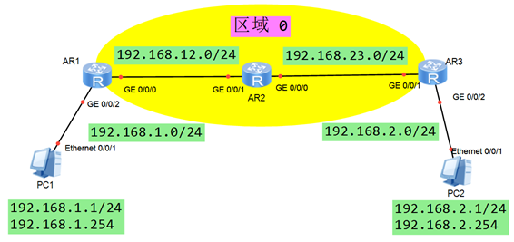
- 如图,配置设备 IP 地址
- 配置 OSPF 协议,所有网段属于区域 0
- 验证 各路由器的邻接表
- 验证 各路由器的 OSPF 路由
- 确保 PC-1 和 PC-2 可以互通
1.2 方案
搭建实验环境,如图-1所示。
 图-1
图-1
1.3 步骤
实现此案例需要按照如下步骤进行。[hidecontent type=”payshow”]
1)配置终端设备 – PC1
- 地址:192.168.1.1
- 掩码:255.255.255.0
- 网关:192.168.1.254
2)配置终端设备 – PC2
- 地址:192.168.2.1
- 掩码:255.255.255.0
- 网关:192.168.2.254
3)配置网络设备 – R1
- <Huawei>system–view
- [Huawei]sysname R1
- [R1]interface GigabitEthernet 0/0/2
- [R1–GigabitEthernet 0/0/2] ip address 192.168.1.254 255.255.255.0
- [R1–GigabitEthernet 0/0/2] quit
- [R1]interface GigabitEthernet 0/0/0
- [R1–GigabitEthernet 0/0/0] ip address 192.168.12.1 255.255.255.0
- [R1–GigabitEthernet 0/0/0] quit
4)配置网络设备 – R2
- <Huawei>system–view
- [Huawei]sysname R2
- [R2]interface gi0/0/0
- [R2–GigabitEthernet 0/0/0] ip address 192.168.23.2 255.255.255.0
- [R2–GigabitEthernet 0/0/0] quit
- [R2]interface gi0/0/1
- [R2–GigabitEthernet 0/0/1] ip address 192.168.12.2 255.255.255.0
- [R2–GigabitEthernet 0/0/1] quit
5)配置网络设备 – R3
- <Huawei>system–view
- [Huawei]sysname R3
- [R3]interface GigabitEthernet 0/0/2
- [R3–GigabitEthernet 0/0/2] ip address 192.168.2.254 255.255.255.0
- [R3–GigabitEthernet 0/0/2] quit
- [R3]interface GigabitEthernet 0/0/1
- [R3–GigabitEthernet 0/0/1] ip address 192.168.23.3 255.255.255.0
- [R3–GigabitEthernet 0/0/1] quit
6)配置 OSPF 区域 0
- [R1]ospf 1 router–id 1.1.1.1
- [R1–ospf-1]area 0
- [R1–ospf-1–area-0.0.0.0]network 192.168.12.0 0.0.0.255
- [R1–ospf-1–area-0.0.0.0]network 192.168.1.0 0.0.0.255
- [R1–ospf-1–area-0.0.0.0]quit
- [R2]ospf 1 router–id 2.2.2.2
- [R2–ospf-1]area 0
- [R2–ospf-1–area-0.0.0.0]network 192.168.12.0 0.0.0.255
- [R2–ospf-1–area-0.0.0.0]network 192.168.23.0 0.0.0.255
- [R2–ospf-1–area-0.0.0.0]quit
- [R3]ospf 1 router–id 3.3.3.3
- [R3–ospf-1]area 0
- [R3–ospf-1–area-0.0.0.0]network 192.168.23.0 0.0.0.255
- [R3–ospf-1–area-0.0.0.0]network 192.168.2.0 0.0.0.255
- [R3–ospf-1–area-0.0.0.0]quit
7)验证 OSPF 邻接表
- [R1]display ospf peer brief
- OSPF Process 1 with Router ID 1.1.1.1
- Peer Statistic Information
- —————————————————————————-
- Area Id Interface Neighbor id State
- 0.0.0.0 GigabitEthernet0/0/0 2.2.2.2 Full
- —————————————————————————-
- [R2]display ospf peer brief
- OSPF Process 1 with Router ID 2.2.2.2
- Peer Statistic Information
- —————————————————————————-
- Area Id Interface Neighbor id State
- 0.0.0.0 GigabitEthernet0/0/1 1.1.1.1 Full
- 0.0.0.0 GigabitEthernet0/0/0 3.3.3.3 Full
- —————————————————————————-
- [R3]display ospf peer brief
- OSPF Process 1 with Router ID 3.3.3.3
- Peer Statistic Information
- —————————————————————————-
- Area Id Interface Neighbor id State
- 0.0.0.0 GigabitEthernet0/0/1 2.2.2.2 Full
- —————————————————————————-
8)验证 OSPF 路由表
- [R1]display ip routing–table protocol ospf
- Route Flags: R – relay, D – download to fib
- ——————————————————————————
- Destination/Mask Proto Pre Cost Flags NextHop Interface
- 192.168.2.0/24 OSPF 10 3 D 192.168.12.2 GigabitEthernet0/0/0
- 192.168.23.0/24 OSPF 10 2 D 192.168.12.2 GigabitEthernet0/0/0
- [R2]display ip routing–table protocol ospf
- Route Flags: R – relay, D – download to fib
- ——————————————————————————
- Destination/Mask Proto Pre Cost Flags NextHop Interface
- 192.168.1.0/24 OSPF 10 2 D 192.168.12.1 GigabitEthernet0/0/1
- 192.168.2.0/24 OSPF 10 2 D 192.168.23.3 GigabitEthernet0/0/0
- [R3]display ip routing–table protocol ospf
- Route Flags: R – relay, D – download to fib
- ——————————————————————————
- Destination/Mask Proto Pre Cost Flags NextHop Interface
- 192.168.1.0/24 OSPF 10 3 D 192.168.23.2 GigabitEthernet0/0/1
- 192.168.12.0/24 OSPF 10 2 D 192.168.23.2 GigabitEthernet0/0/1
9)测试 PC-1 与 PC-2 之间的连通性
- PC-1>ping 192.168.2.1
- Ping 192.168.2.1: 32 data bytes, Press Ctrl_C to break
- From 192.168.2.1: bytes=32 seq=1 ttl=125 time=31 ms
- From 192.168.2.1: bytes=32 seq=2 ttl=125 time=31 ms
- From 192.168.2.1: bytes=32 seq=3 ttl=125 time=16 ms
- From 192.168.2.1: bytes=32 seq=4 ttl=125 time=16 ms
- From 192.168.2.1: bytes=32 seq=5 ttl=125 time=31 ms
- — 192.168.2.1 ping statistics —
- 5 packet(s) transmitted
- 5 packet(s) received
- 0.00% packet loss
- round–trip min/avg/max = 16/25/31 ms
- PC-2>ping 192.168.1.1
- Ping 192.168.1.1: 32 data bytes, Press Ctrl_C to break
- From 192.168.1.1: bytes=32 seq=1 ttl=125 time=16 ms
- From 192.168.1.1: bytes=32 seq=2 ttl=125 time=31 ms
- From 192.168.1.1: bytes=32 seq=3 ttl=125 time=31 ms
- From 192.168.1.1: bytes=32 seq=4 ttl=125 time=32 ms
- From 192.168.1.1: bytes=32 seq=5 ttl=125 time=31 ms
- — 192.168.1.1 ping statistics —
- 5 packet(s) transmitted
- 5 packet(s) received
- 0.00% packet loss
- round–trip min/avg/max = 16/28/32 ms
2 案例:OSPF邻居表解析
2.1 问题
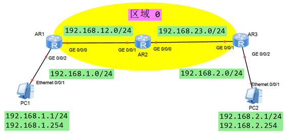
- 如图,配置设备 IP 地址
- 配置 OSPF 协议,所有网段属于区域 0
- 验证 各路由器的邻接表
- 确保 R1-R2之间不需要DR
- 确保 R2-R3之间,R2是DR
2.2 方案
搭建实验环境,如图-2所示。
 图-2
图-2
2.3 步骤
实现此案例需要按照如下步骤进行。
1)配置终端设备 – PC1
- 地址:192.168.1.1
- 掩码:255.255.255.0
- 网关:192.168.1.254
2)配置终端设备 – PC2
- 地址:192.168.2.1
- 掩码:255.255.255.0
- 网关:192.168.2.254
3)配置网络设备 – R1
- <Huawei>system–view
- [Huawei]sysname R1
- [R1]interface GigabitEthernet 0/0/2
- [R1–GigabitEthernet 0/0/2] ip address 192.168.1.254 255.255.255.0
- [R1–GigabitEthernet 0/0/2] quit
- [R1]interface GigabitEthernet 0/0/0
- [R1–GigabitEthernet 0/0/0] ip address 192.168.12.1 255.255.255.0
- [R1–GigabitEthernet 0/0/0] quit
4)配置网络设备 – R2
- <Huawei>system–view
- [Huawei]sysname R2
- [R2]interface gi0/0/0
- [R2–GigabitEthernet 0/0/0] ip address 192.168.23.2 255.255.255.0
- [R2–GigabitEthernet 0/0/0] quit
- [R2]interface gi0/0/1
- [R2–GigabitEthernet 0/0/1] ip address 192.168.12.2 255.255.255.0
- [R2–GigabitEthernet 0/0/1] quit
5)配置网络设备 – R3
- <Huawei>system–view
- [Huawei]sysname R3
- [R3]interface GigabitEthernet 0/0/2
- [R3–GigabitEthernet 0/0/2] ip address 192.168.2.254 255.255.255.0
- [R3–GigabitEthernet 0/0/2] quit
- [R3]interface GigabitEthernet 0/0/1
- [R3–GigabitEthernet 0/0/1] ip address 192.168.23.3 255.255.255.0
- [R3–GigabitEthernet 0/0/1] quit
6)配置 OSPF 区域 0
- [R1]ospf 1 router–id 1.1.1.1
- [R1–ospf-1]area 0
- [R1–ospf-1–area-0.0.0.0]network 192.168.12.0 0.0.0.255
- [R1–ospf-1–area-0.0.0.0]network 192.168.1.0 0.0.0.255
- [R1–ospf-1–area-0.0.0.0]quit
- [R2]ospf 1 router–id 2.2.2.2
- [R2–ospf-1]area 0
- [R2–ospf-1–area-0.0.0.0]network 192.168.12.0 0.0.0.255
- [R2–ospf-1–area-0.0.0.0]network 192.168.23.0 0.0.0.255
- [R2–ospf-1–area-0.0.0.0]quit
- [R3]ospf 1 router–id 3.3.3.3
- [R3–ospf-1]area 0
- [R3–ospf-1–area-0.0.0.0]network 192.168.23.0 0.0.0.255
- [R3–ospf-1–area-0.0.0.0]network 192.168.2.0 0.0.0.255
- [R3–ospf-1–area-0.0.0.0]quit
7)验证 OSPF 邻接表
- [R1]display ospf peer brief
- OSPF Process 1 with Router ID 1.1.1.1
- Peer Statistic Information
- —————————————————————————-
- Area Id Interface Neighbor id State
- 0.0.0.0 GigabitEthernet0/0/0 2.2.2.2 Full
- —————————————————————————-
- [R2]display ospf peer brief
- OSPF Process 1 with Router ID 2.2.2.2
- Peer Statistic Information
- —————————————————————————-
- Area Id Interface Neighbor id State
- 0.0.0.0 GigabitEthernet0/0/1 1.1.1.1 Full
- 0.0.0.0 GigabitEthernet0/0/0 3.3.3.3 Full
- —————————————————————————-
- [R3]display ospf peer brief
- OSPF Process 1 with Router ID 3.3.3.3
- Peer Statistic Information
- —————————————————————————-
- Area Id Interface Neighbor id State
- 0.0.0.0 GigabitEthernet0/0/1 2.2.2.2 Full
- —————————————————————————-
8)修改R1-R2之间的网络类型为P2P
- [R1]interface GigabitEthernet 0/0/0
- [R1–GigabitEthernet 0/0/0] ospf network–type p2p
- [R1–GigabitEthernet 0/0/0] quit
- [R2]interface GigabitEthernet 0/0/1
- [R2–GigabitEthernet 0/0/1] ospf network–type p2p
- [R2–GigabitEthernet 0/0/1] quit
9)确保R2-R3之间,R2是DR
- [R3]interface GigabitEthernet 0/0/1
- [R3–GigabitEthernet 0/0/1] ospf dr–priority 0
- [R3–GigabitEthernet 0/0/1] quit
3 案例:OSPF多区域的配置
3.1 问题
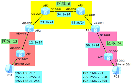
- 如图配置IP地址,设置OSPF区域
- 确保R1和R2之间不选举DR,R5为区域56的DR,为区域0的BDR
- 验证R2和R5的角色为 ABR
- 确保PC-1和 PC-2可以互通
3.2 方案
搭建实验环境,如图-3所示。
 图-3
图-3
3.3 步骤
实现此案例需要按照如下步骤进行。
1)配置IP地址,设置OSPF区域
- <Huawei>undo terminal monitor
- <Huawei>system–view
- [Huawei]sysname R1
- [R1]interface GigabitEthernet 0/0/0
- [R1–GigabitEthernet0/0/0]ip add 192.168.12.1 24
- [R1–GigabitEthernet0/0/0]quit
- [R1]interface GigabitEthernet 0/0/2
- [R1–GigabitEthernet0/0/2]ip add 192.168.1.1 24
- [R1–GigabitEthernet0/0/2]quit
- [R1]ospf 1 router–id 1.1.1.1
- [R1–ospf-1]area 12
- [R1–ospf-1–area-0.0.0.12]network 192.168.12.0 0.0.0.255
- [R1–ospf-1–area-0.0.0.12]network 192.168.1.0 0.0.0.255
- [R1–ospf-1–area-0.0.0.12]quit
- <Huawei>undo terminal monitor
- <Huawei>system–view
- [Huawei]sysname R2
- [R2]interface GigabitEthernet 0/0/1
- [R2–GigabitEthernet0/0/1]ip add 192.168.12.2 24
- [R2–GigabitEthernet0/0/1]quit
- [R2]interface GigabitEthernet 0/0/0
- [R2–GigabitEthernet0/0/0]ip add 192.168.23.2 24
- [R2–GigabitEthernet0/0/0]quit
- [R2]ospf 1 router–id 2.2.2.2
- [R2–ospf-1]area 12
- [R2–ospf-1–area-0.0.0.12]network 192.168.12.0 0.0.0.255
- [R2–ospf-1–area-0.0.0.12]quit
- [R2–ospf-1]area 0
- [R2–ospf-1–area-0.0.0.0]network 192.168.23.0 0.0.0.255
- [R2–ospf-1–area-0.0.0.0]quit
- <Huawei>undo terminal monitor
- <Huawei>system–view
- [Huawei]sysname R3
- [R3]interface GigabitEthernet 0/0/1
- [R3–GigabitEthernet0/0/1]ip add 192.168.23.3 24
- [R3–GigabitEthernet0/0/1]quit
- [R3]interface GigabitEthernet 0/0/0
- [R3–GigabitEthernet0/0/0]ip add 192.168.34.3 24
- [R3–GigabitEthernet0/0/0]quit
- [R3]ospf 1 router–id 3.3.3.3
- [R3–ospf-1]area 0
- [R3–ospf-1–area-0.0.0.0]network 192.168.23.0 0.0.0.255
- [R3–ospf-1–area-0.0.0.0]network 192.168.34.0 0.0.0.255
- [R3–ospf-1–area-0.0.0.0]quit
- <Huawei>undo terminal monitor
- <Huawei>system–view
- [Huawei]sysname R4
- [R4]interface GigabitEthernet 0/0/1
- [R4–GigabitEthernet0/0/1]ip add 192.168.34.4 24
- [R4–GigabitEthernet0/0/1]quit
- [R4]interface GigabitEthernet 0/0/0
- [R4–GigabitEthernet0/0/0]ip add 192.168.45.4 24
- [R4–GigabitEthernet0/0/0]quit
- [R4]ospf 1 router–id 4.4.4.4
- [R4–ospf-1]area 0
- [R4–ospf-1–area-0.0.0.0]network 192.168.45.0 0.0.0.255
- [R4–ospf-1–area-0.0.0.0]network 192.168.34.0 0.0.0.255
- [R4–ospf-1–area-0.0.0.0]quit
- <Huawei>undo terminal monitor
- <Huawei>system–view
- [Huawei]sysname R5
- [R5]interface GigabitEthernet 0/0/1
- [R5–GigabitEthernet0/0/1]ip add 192.168.45.5 24
- [R5–GigabitEthernet0/0/1]quit
- [R5]interface GigabitEthernet 0/0/0
- [R5–GigabitEthernet0/0/0]ip add 192.168.56.5 24
- [R5–GigabitEthernet0/0/0]quit
- [R5]ospf 1 router–id 5.5.5.5
- [R5–ospf-1]area 56
- [R5–ospf-1–area-0.0.0.56]network 192.168.56.0 0.0.0.255
- [R5–ospf-1–area-0.0.0.56]quit
- [R5–ospf-1]area 0
- [R5–ospf-1–area-0.0.0.0]network 192.168.45.0 0.0.0.255
- [R5–ospf-1–area-0.0.0.0]quit
- <Huawei>undo terminal monitor
- <Huawei>system–view
- [Huawei]sysname R6
- [R6]interface GigabitEthernet 0/0/1
- [R6–GigabitEthernet0/0/1]ip add 192.168.56.6 24
- [R6–GigabitEthernet0/0/1]quit
- [R6]interface GigabitEthernet 0/0/2
- [R6–GigabitEthernet0/0/2]ip add 192.168.2.254 24
- [R6–GigabitEthernet0/0/2]quit
- [R6]ospf 1 router–id 6.6.6.6
- [R6–ospf-1]area 56
- [R6–ospf-1–area-0.0.0.56]network 192.168.56.0 0.0.0.255
- [R6–ospf-1–area-0.0.0.56]network 192.168.2.0 0.0.0.255
- [R6–ospf-1–area-0.0.0.56]quit
2)设置R1和R2之间不选举DR配置
- [R1]interface GigabitEthernet 0/0/0
- [R1–GigabitEthernet0/0/0]ospf network–type p2p
- [R1–GigabitEthernet0/0/0]quit
- [R2]interface GigabitEthernet 0/0/1
- [R2–GigabitEthernet0/0/1]ospf network–type p2p
- [R2–GigabitEthernet0/0/1]quit
3)配置R5 为 区域 56 的 DR
- [R6]interface GigabitEthernet 0/0/1
- [R6–GigabitEthernet0/0/1] ospf dr–priority 0
- [R6–GigabitEthernet0/0/1]quit
4)配置 R5 为 区域 0 的 BDR
- [R4]interface GigabitEthernet 0/0/0
- [R4–GigabitEthernet0/0/0]ospf dr–priority 10
- [R4–GigabitEthernet0/0/0]quit
5)验证R2和R5是 ABR 的 角色
- [R2]display ospf brief
- OSPF Process 1 with Router ID 2.2.2.2
- OSPF Protocol Information
- RouterID: 2.2.2.2 Border Router: AREA // R2 为 ABR
- Multi–VPN–Instance is not enabled
- Global DS–TE Mode: Non–Standard IETF Mode
- (……)
- [R5]display ospf brief
- OSPF Process 1 with Router ID 5.5.5.5
- OSPF Protocol Information
- RouterID: 5.5.5.5 Border Router: AREA // R2 为 ABR
- Multi–VPN–Instance is not enabled
- Global DS–TE Mode: Non–Standard IETF Mode
- (……)
6)确保PC-1和 PC-2互通
- PC-1>ping 192.168.2.1
- Ping 192.168.2.1: 32 data bytes, Press Ctrl_C to break
- From 192.168.2.1: bytes=32 seq=1 ttl=125 time=31 ms
- From 192.168.2.1: bytes=32 seq=2 ttl=125 time=31 ms
- From 192.168.2.1: bytes=32 seq=3 ttl=125 time=16 ms
- From 192.168.2.1: bytes=32 seq=4 ttl=125 time=16 ms
- From 192.168.2.1: bytes=32 seq=5 ttl=125 time=31 ms
- — 192.168.2.1 ping statistics —
- 5 packet(s) transmitted
- 5 packet(s) received
- 0.00% packet loss
- round–trip min/avg/max = 16/25/31 ms
- PC-2>ping 192.168.1.1
- Ping 192.168.1.1: 32 data bytes, Press Ctrl_C to break
- From 192.168.1.1: bytes=32 seq=1 ttl=125 time=16 ms
- From 192.168.1.1: bytes=32 seq=2 ttl=125 time=31 ms
- From 192.168.1.1: bytes=32 seq=3 ttl=125 time=31 ms
- From 192.168.1.1: bytes=32 seq=4 ttl=125 time=32 ms
- From 192.168.1.1: bytes=32 seq=5 ttl=125 time=31 ms
- — 192.168.1.1 ping statistics —
- 5 packet(s) transmitted
- 5 packet(s) received
- 0.00% packet loss
- round–trip min/avg/max = 16/28/32 ms
4 案例:OSPF 综合案例
4.1 问题
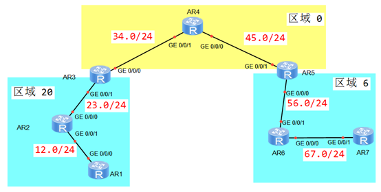
- 如图配置IP地址,规划OSPF区域
- 配置每个OSPF路由器的 RID 为 10.10.X.X (X为路由器号码)
- 确保区域20中,只有1个DR,R3为DR
- 确保区域0中,没有 DR
- 确保区域0中使用不同网络类型
- 确保 R6上,192.168.12.0/24的 cost为10
- 确保 R2上,192.168.67.0/24的 cost 为 23
- 配置 ACL,确保 R6-R7 无法建立 OSPF 邻居
4.2 方案
搭建实验环境,如图-4所示。
 图-4
图-4
4.3 步骤
实现此案例需要按照如下步骤进行。
1)配置IP地址,设置OSPF区域
- <Huawei>undo terminal monitor
- <Huawei>system–view
- [Huawei]sysname R1
- [R1]interface GigabitEthernet 0/0/0
- [R1–GigabitEthernet0/0/0]ip add 192.168.12.1 24
- [R1–GigabitEthernet0/0/0]quit
- [R1]ospf 1 router–id 1.1.1.1
- [R1–ospf-1]area 20
- [R1–ospf-1–area-0.0.0.20]network 192.168.12.0 0.0.0.255
- [R1–ospf-1–area-0.0.0.20]quit
- <Huawei>undo terminal monitor
- <Huawei>system–view
- [Huawei]sysname R2
- [R2]interface GigabitEthernet 0/0/1
- [R2–GigabitEthernet0/0/1]ip add 192.168.12.2 24
- [R2–GigabitEthernet0/0/1]quit
- [R2]interface GigabitEthernet 0/0/0
- [R2–GigabitEthernet0/0/0]ip add 192.168.23.2 24
- [R2–GigabitEthernet0/0/0]quit
- [R2]ospf 1 router–id 2.2.2.2
- [R2–ospf-1]area 20
- [R2–ospf-1–area-0.0.0.20]network 192.168.12.0 0.0.0.255
- [R2–ospf-1–area-0.0.0.20]network 192.168.23.0 0.0.0.255
- [R2–ospf-1–area-0.0.0.20]quit
- <Huawei>undo terminal monitor
- <Huawei>system–view
- [Huawei]sysname R3
- [R3]interface GigabitEthernet 0/0/1
- [R3–GigabitEthernet0/0/1]ip add 192.168.23.3 24
- [R3–GigabitEthernet0/0/1]quit
- [R3]interface GigabitEthernet 0/0/0
- [R3–GigabitEthernet0/0/0]ip add 192.168.34.3 24
- [R3–GigabitEthernet0/0/0]quit
- [R3]ospf 1 router–id 3.3.3.3
- [R3–ospf-1]area 0
- [R3–ospf-1–area-0.0.0.0]network 192.168.34.0 0.0.0.255
- [R3–ospf-1–area-0.0.0.0]quit
- [R3–ospf-1]area 20
- [R3–ospf-1–area-0.0.0.20]network 192.168.23.0 0.0.0.255
- [R3–ospf-1–area-0.0.0.0]quit
- <Huawei>undo terminal monitor
- <Huawei>system–view
- [Huawei]sysname R4
- [R4]interface GigabitEthernet 0/0/1
- [R4–GigabitEthernet0/0/1]ip add 192.168.34.4 24
- [R4–GigabitEthernet0/0/1]quit
- [R4]interface GigabitEthernet 0/0/0
- [R4–GigabitEthernet0/0/0]ip add 192.168.45.4 24
- [R4–GigabitEthernet0/0/0]quit
- [R4]ospf 1 router–id 4.4.4.4.
- [R4–ospf-1]area 0
- [R4–ospf-1–area-0.0.0.0]network 192.168.45.0 0.0.0.255
- [R4–ospf-1–area-0.0.0.0]network 192.168.34.0 0.0.0.255
- [R4–ospf-1–area-0.0.0.0]quit
- <Huawei>undo terminal monitor
- <Huawei>system–view
- [Huawei]sysname R5
- [R5]interface GigabitEthernet 0/0/1
- [R5–GigabitEthernet0/0/1]ip add 192.168.45.5 24
- [R5–GigabitEthernet0/0/1]quit
- [R5]interface GigabitEthernet 0/0/0
- [R5–GigabitEthernet0/0/0]ip add 192.168.56.5 24
- [R5–GigabitEthernet0/0/0]quit
- [R5]ospf 1 router–id 5.5.5.5
- [R5–ospf-1]area 6
- [R5–ospf-1–area-0.0.0.6]network 192.168.56.0 0.0.0.255
- [R5–ospf-1–area-0.0.0.6]quit
- [R5–ospf-1]area 0
- [R5–ospf-1–area-0.0.0.0]network 192.168.45.0 0.0.0.255
- [R5–ospf-1–area-0.0.0.0]quit
- <Huawei>undo terminal monitor
- <Huawei>system–view
- [Huawei]sysname R6
- [R6]interface GigabitEthernet 0/0/1
- [R6–GigabitEthernet0/0/1]ip add 192.168.56.6 24
- [R6–GigabitEthernet0/0/1]quit
- [R6]interface GigabitEthernet 0/0/0
- [R6–GigabitEthernet0/0/0]ip add 192.168.67.6 24
- [R6–GigabitEthernet0/0/0]quit
- [R6]ospf 1 router–id 6.6.6.6
- [R6–ospf-1]area 6
- [R6–ospf-1–area-0.0.0.6]network 192.168.56.0 0.0.0.255
- [R6–ospf-1–area-0.0.0.6]network 192.168.67.0 0.0.0.255
- [R6–ospf-1–area-0.0.0.6]quit
- <Huawei>undo terminal monitor
- <Huawei>system–view
- [Huawei]sysname R7
- [R7]interface GigabitEthernet 0/0/1
- [R7–GigabitEthernet0/0/1]ip add 192.168.67.7 24
- [R7–GigabitEthernet0/0/1]quit
- [R7]ospf 1 router–id 7.7.7.7
- [R7–ospf-1]area 6
- [R7–ospf-1–area-0.0.0.6]network 192.168.67.0 0.0.0.255
- [R7–ospf-1–area-0.0.0.6]quit
2)配置区域20中的DR
- [R1]interface GigabitEthernet 0/0/0
- [R1–GigabitEthernet0/0/0]ospf network–type p2p
- [R1–GigabitEthernet0/0/0]quit
- [R2]interface GigabitEthernet 0/0/1
- [R2–GigabitEthernet0/0/1]ospf network–type p2p
- [R2–GigabitEthernet0/0/1]quit
- [R2]interface GigabitEthernet 0/0/0
- [R2–GigabitEthernet0/0/0]ospf dr–priority 0
- [R2–GigabitEthernet0/0/0]quit
3)确保区域0中没有DR
- [R3]interface GigabitEthernet 0/0/0
- [R3–GigabitEthernet0/0/0]ospf network–type p2p
- [R3–GigabitEthernet0/0/0]quit
- [R4]interface GigabitEthernet 0/0/1
- [R4–GigabitEthernet0/0/1]ospf network–type p2p
- [R4–GigabitEthernet0/0/1]quit
- [R4]interface GigabitEthernet 0/0/0
- [R4–GigabitEthernet0/0/0]ospf network–type p2mp
- [R4–GigabitEthernet0/0/0]quit
- [R5]interface GigabitEthernet 0/0/1
- [R5–GigabitEthernet0/0/1]ospf network–type p2mp
- [R5–GigabitEthernet0/0/1]quit
4)确保R6的路由表中 192.168.12.0/24 的 cost 为10
- [R6]interface GigabitEthernet 0/0/1
- [R6–GigabitEthernet0/0/1]ospf cost 6
- [R6–GigabitEthernet0/0/1]quit
5)确保R2的路由表中 192.168.67.0/24 的 cost 为23
- [R2]interface GigabitEthernet 0/0/1
- [R2–GigabitEthernet0/0/1]ospf cost 19
- [R2–GigabitEthernet0/0/1]quit
6)配置ACL,确保R6和R7之间无法建立OSPF邻居
- [R7]acl 3000
- [R7–acl–adv-3000]rule 10 deny ospf source 192.168.67.6 0.0.0.0 destination 224.0.0.5 0
- [R7]interface GigabitEthernet 0/0/1
- [R7–GigabitEthernet0/0/1]traffic–filter inbound acl 3000[/hidecontent]

