1 案例:配置NSSA区域
1.1 问题
- 如图配置设备IP地址和OSPF区域
- R4去往ISP,使用的是静态的默认路由
- R1去往合作公司,使用的也是静态路由,仅需要访问 PC-1 即可
- 区域 123 不允许出现 5类 LSA
- 确保 PC-1 和 Server-1 互通
1.2 方案
搭建实验环境,如图-1所示。
 图-1
图-1
1.3 步骤
实现此案例需要按照如下步骤进行。[hidecontent type=”payshow”]
1)配置终端设备
- PC-1:
- 192.168.10.1
- 255.255.255.0
- 192.168.10.254
- Server-1:
- 192.168.20.1
- 255.255.255.0
- 192.168.20.254
2)配置IP地址和基本OSPF
- <Huawei>undo terminal monitor
- <Huawei>system–view
- [Huawei]sysname R1
- [R1]interface GigabitEthernet 0/0/0
- [R1–GigabitEthernet0/0/0]ip address 192.168.12.1 24
- [R1–GigabitEthernet0/0/0]quit
- [R1]interface GigabitEthernet 0/0/1
- [R1–GigabitEthernet0/0/1]ip address 192.168.16.1 24
- [R1–GigabitEthernet0/0/1]quit
- [R1]ospf 1 router–id 1.1.1.1
- [R1–ospf-1]area 123
- [R1–ospf-1–area-0.0.0.123]network 192.168.12.0 0.0.0.255
- [R1–ospf-1–area-0.0.0.123]quit
- [R1–ospf-1]quit
- <Huawei>undo terminal monitor
- <Huawei>system–view
- [Huawei]sysname R2
- [R2]interface GigabitEthernet 0/0/1
- [R2–GigabitEthernet0/0/1]ip address 192.168.12.2 24
- [R2–GigabitEthernet0/0/1]q
- [R2]interface GigabitEthernet 0/0/0
- [R2–GigabitEthernet0/0/0]ip address 192.168.23.2 24
- [R2–GigabitEthernet0/0/0]q
- [R2]ospf 1 router–id 2.2.2.2
- [R2–ospf-1]area 123
- [R2–ospf-1–area-0.0.0.123]network 192.168.12.0 0.0.0.255
- [R2–ospf-1–area-0.0.0.123]network 192.168.23.0 0.0.0.255
- [R2–ospf-1–area-0.0.0.123]quit
- [R2–ospf-1]quit
- <Huawei>undo terminal monitor
- <Huawei>system–view
- [Huawei]sysname R3
- [R3]interface GigabitEthernet 0/0/1
- [R3–GigabitEthernet0/0/1]ip address 192.168.23.3 24
- [R3–GigabitEthernet0/0/1]quit
- [R3]interface GigabitEthernet 0/0/0
- [R3–GigabitEthernet0/0/0]ip address 192.168.34.3 24
- [R3–GigabitEthernet0/0/0]quit
- [R3]ospf 1 router–id 3.3.3.3
- [R3–ospf-1]area 123
- [R3–ospf-1–area-0.0.0.123]network 192.168.23.0 0.0.0.255
- [R3–ospf-1–area-0.0.0.123]quit
- [R3–ospf-1]area 0
- [R3–ospf-1–area-0.0.0.0]network 192.168.34.0 0.0.0.255
- [R3–ospf-1]quit
- <Huawei>undo terminal monitor
- <Huawei>system–view
- [Huawei]sysname R4
- [R4]interface GigabitEthernet 0/0/1
- [R4–GigabitEthernet0/0/1]ip address 192.168.34.4 24
- [R4–GigabitEthernet0/0/1]quit
- [R4]interface GigabitEthernet 0/0/0
- [R4–GigabitEthernet0/0/0]ip address 192.168.45.4 24
- [R4–GigabitEthernet0/0/0]quit
- [R4]ospf 1 router–id 4.4.4.4
- [R4–ospf-1]area 0
- [R4–ospf-1–area-0.0.0.0]network 192.168.34.0 0.0.0.255
- [R4–ospf-1]quit
- <Huawei>undo terminal monitor
- <Huawei>system–view
- [Huawei]sysname ISP
- [ISP]interface GigabitEthernet 0/0/1
- [ISP–GigabitEthernet0/0/1]ip address 192.168.45.5 24
- [ISP–GigabitEthernet0/0/1]quit
- [ISP]interface GigabitEthernet 0/0/2
- [ISP–GigabitEthernet0/0/2]ip address 192.168.20.254 24
- [ISP–GigabitEthernet0/0/2]quit
- [ISP] ip route–static 192.168.0.0 16 192.168.45.4
- <Huawei>undo terminal monitor
- <Huawei>system–view
- [Huawei]sysname R6
- [R6]interface GigabitEthernet 0/0/0
- [R6–GigabitEthernet0/0/1]ip address 192.168.16.6 24
- [R6–GigabitEthernet0/0/1]quit
- [R6]interface GigabitEthernet 0/0/2
- [R6–GigabitEthernet0/0/2]ip address 192.168.10.254 24
- [R6–GigabitEthernet0/0/2]quit
- [R6] ip route–static 192.168.0.0 255.255.0.0 192.168.16.1
3)配置区域123为 NSSA 区域
- [R1]ospf 1
- [R1–ospf-1]area 123
- [R1–ospf-1–area-0.0.0.123]nssa
- [R1–ospf-1–area-0.0.0.123]quit
- [R2]ospf 1
- [R2–ospf-1]area 123
- [R2–ospf-1–area-0.0.0.123]nssa
- [R2–ospf-1–area-0.0.0.123]quit
- [R3]ospf 1
- [R3–ospf-1]area 123
- [R3–ospf-1–area-0.0.0.123]nssa
- [R3–ospf-1–area-0.0.0.123]quit
4)配置 R1 引入 合作公司的外部路由
- [R1]ip route–static 192.168.10.0 24 192.168.16.6
- [R1]ospf 1
- [R1–ospf-1]import–route static
5)配置 R4 引入 去往外部网络的路由
- [R4]ip route–static 0.0.0.0 0 192.168.45.5
- [R4]ospf 1
- [R4–ospf-1]default–route–advertise
6)测试 PC1 和 Server-1的连通性
- PC-1>ping 192.168.20.1
- Ping 192.168.20.1: 32 data bytes, Press Ctrl_C to break
- From 192.168.20.1: bytes=32 seq=1 ttl=125 time=31 ms
- From 192.168.20.1: bytes=32 seq=2 ttl=125 time=31 ms
- From 192.168.20.1: bytes=32 seq=3 ttl=125 time=16 ms
- From 192.168.20.1: bytes=32 seq=4 ttl=125 time=16 ms
- From 192.168.20.1: bytes=32 seq=5 ttl=125 time=31 ms
- — 192.168.20.1 ping statistics —
- 5 packet(s) transmitted
2 案例:配置OSPF汇总
2.1 问题
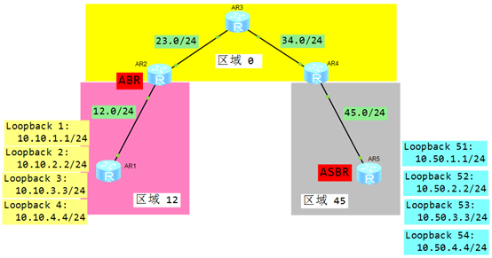
- 对区域 12 进行3类LSA汇总,汇总后为 10.10.0.0/16
- 对区域 45 的直连链路进行5类汇总,进行精确汇总
2.2 方案
搭建实验环境,如图-2所示。
 图-2
图-2
2.3 步骤
实现此案例需要按照如下步骤进行。
1)配置IP地址和OSPF
- <Huawei>undo terminal monitor
- <Huawei>system–view
- [Huawei]sysname R1
- [R1]interface GigabitEthernet 0/0/0
- [R1–GigabitEthernet0/0/0]ip add 192.168.12.1 24
- [R1–GigabitEthernet0/0/0]quit
- [R1]interface LoopBack 1
- [R1–LoopBack1]ip address 10.10.1.1 24
- [R1–LoopBack1]quit
- [R1]interface LoopBack 2
- [R1–LoopBack2]ip address 10.10.2.2 24
- [R1–LoopBack2]quit
- [R1]interface LoopBack 3
- [R1–LoopBack3]ip address 10.10.3.3 24
- [R1–LoopBack3]quit
- [R1]interface LoopBack 4
- [R1–LoopBack4]ip address 10.10.4.4 24
- [R1–LoopBack4]quit
- [R1]ospf 1 router–id 1.1.1.1
- [R1–ospf-1]area 12
- [R1–ospf-1–area-0.0.0.12]network 192.168.12.0 0.0.0.255
- [R1–ospf-1–area-0.0.0.12]network 10.10.1.0 0.0.0.255
- [R1–ospf-1–area-0.0.0.12]network 10.10.2.0 0.0.0.255
- [R1–ospf-1–area-0.0.0.12]network 10.10.3.0 0.0.0.255
- [R1–ospf-1–area-0.0.0.12]network 10.10.4.0 0.0.0.255
- [R1–ospf-1–area-0.0.0.12]quit
- <Huawei>undo terminal monitor
- <Huawei>system–view
- [Huawei]sysname R2
- [R2]interface GigabitEthernet 0/0/1
- [R2–GigabitEthernet0/0/1]ip add 192.168.12.2 24
- [R2–GigabitEthernet0/0/1]quit
- [R2]interface GigabitEthernet 0/0/0
- [R2–GigabitEthernet0/0/0]ip add 192.168.23.2 24
- [R2–GigabitEthernet0/0/0]quit
- [R2]ospf 1 router–id 2.2.2.2
- [R2–ospf-1]area 12
- [R2–ospf-1–area-0.0.0.12]network 192.168.12.0 0.0.0.255
- [R2–ospf-1–area-0.0.0.12]quit
- [R2–ospf-1]area 0
- [R2–ospf-1–area-0.0.0.0]network 192.168.23.0 0.0.0.255
- [R2–ospf-1–area-0.0.0.0]quit
- <Huawei>undo terminal monitor
- <Huawei>system–view
- [Huawei]sysname R3
- [R3]interface GigabitEthernet 0/0/1
- [R3–GigabitEthernet0/0/1]ip add 192.168.23.3 24
- [R3–GigabitEthernet0/0/1]quit
- [R3]interface GigabitEthernet 0/0/0
- [R3–GigabitEthernet0/0/0]ip add 192.168.34.3 24
- [R3–GigabitEthernet0/0/0]quit
- [R3]ospf 1 router–id 3.3.3.3
- [R3–ospf-1]area 0
- [R3–ospf-1–area-0.0.0.0]network 192.168.23.0 0.0.0.255
- [R3–ospf-1–area-0.0.0.0]network 192.168.34.0 0.0.0.255
- [R3–ospf-1–area-0.0.0.0]quit
- <Huawei>undo terminal monitor
- <Huawei>system–view
- [Huawei]sysname R4
- [R4]interface GigabitEthernet 0/0/1
- [R4–GigabitEthernet0/0/1]ip add 192.168.34.4 24
- [R4–GigabitEthernet0/0/1]quit
- [R4]interface GigabitEthernet 0/0/0
- [R4–GigabitEthernet0/0/0]ip add 192.168.45.4 24
- [R4–GigabitEthernet0/0/0]quit
- [R4]ospf 1 router–id 4.4.4.4
- [R4–ospf-1]area 0
- [R4–ospf-1–area-0.0.0.0]network 192.168.34.0 0.0.0.255
- [R4–ospf-1–area-0.0.0.0]quit
- [R4–ospf-1]area 45
- [R4–ospf-1–area-0.0.0.0]network 192.168.45.0 0.0.0.255
- <Huawei>undo terminal monitor
- <Huawei>system–view
- [Huawei]sysname R5
- [R5]interface GigabitEthernet 0/0/1
- [R5–GigabitEthernet0/0/1]ip add 192.168.45.5 24
- [R5–GigabitEthernet0/0/1]quit
- [R1]interface LoopBack 51
- [R1–LoopBack1]ip address 10.50.1.1 24
- [R1–LoopBack1]quit
- [R1]interface LoopBack 52
- [R1–LoopBack2]ip address 10.50.2.2 24
- [R1–LoopBack2]quit
- [R1]interface LoopBack 53
- [R1–LoopBack3]ip address 10.50.3.3 24
- [R1–LoopBack3]quit
- [R1]interface LoopBack 54
- [R1–LoopBack4]ip address 10.50.4.4 24
- [R1–LoopBack4]quit
- [R5]ospf 1 router–id 5.5.5.5
- [R5–ospf-1]import–route direct
- [R5–ospf-1]area 45
- [R5–ospf-1–area-0.0.0.56]network 192.168.45.0 0.0.0.255
- [R5–ospf-1–area-0.0.0.56]quit
2)对区域12进行3类LSA汇总
- [R2]ospf 1
- [R2–ospf-1]area 12
- [R2–ospf-1–area-0.0.0.12]abr–summary 10.10.0.0 255.255.0.0
3)对区域45的5类LSA进行精确汇总
- [R5]ospf 1
- [R5–ospf-1]asbr–summary 10.50.0.0 255.255.248.0
3 案例:OSPF虚链路配置
3.1 问题
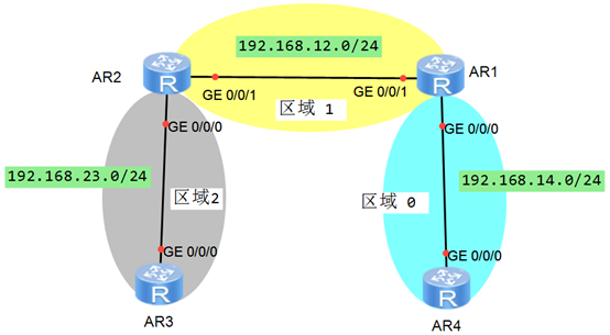
- 公司网络扩容,新区域与骨干区域无法相连
- 通过配置虚链路解决问题
3.2 方案
搭建实验环境,如图-3所示。
 图-3
图-3
3.3 步骤
实现此案例需要按照如下步骤进行。
1)配置IP地址和OSPF网络
- <Huawei>undo terminal monitor
- <Huawei>system–view
- [Huawei]sysname R1
- [R1]interface GigabitEthernet 0/0/0
- [R1–GigabitEthernet0/0/0]ip add 192.168.14.1 24
- [R1–GigabitEthernet0/0/0]quit
- [R1]interface GigabitEthernet 0/0/1
- [R1–GigabitEthernet0/0/1]ip add 192.168.12.1 24
- [R1–GigabitEthernet0/0/1]quit
- [R1]ospf 1 router–id 1.1.1.1
- [R1–ospf-1]area 0
- [R1–ospf-1–area-0.0.0.0]network 192.168.14.0 0.0.0.255
- [R1–ospf-1–area-0.0.0.0]quit
- [R1–ospf-1]area 1
- [R1–ospf-1–area-0.0.0.1]network 192.168.12.0 0.0.0.255
- [R1–ospf-1–area-0.0.0.1]quit
- <Huawei>undo terminal monitor
- <Huawei>system–view
- [Huawei]sysname R4
- [R4]interface GigabitEthernet 0/0/0
- [R4–GigabitEthernet0/0/0]ip add 192.168.14.4 24
- [R4–GigabitEthernet0/0/0]quit
- [R4]ospf 1 router–id 4.4.4.4
- [R4–ospf-1]area 0
- [R4–ospf-1–area-0.0.0.0]network 192.168.14.0 0.0.0.255
- [R4–ospf-1–area-0.0.0.0]quit
- <Huawei>undo terminal monitor
- <Huawei>system–view
- [Huawei]sysname R2
- [R2]interface GigabitEthernet 0/0/1
- [R2–GigabitEthernet0/0/1]ip add 192.168.12.2 24
- [R2–GigabitEthernet0/0/1]quit
- [R2]interface GigabitEthernet 0/0/0
- [R2–GigabitEthernet0/0/0]ip add 192.168.23.2 24
- [R2–GigabitEthernet0/0/0]quit
- [R2]ospf 1 router–id 2.2.2.2
- [R2–ospf-1]area 1
- [R2–ospf-1–area-0.0.0.1]network 192.168.12.0 0.0.0.255
- [R2–ospf-1–area-0.0.0.1]quit
- [R2–ospf-1]area 2
- [R2–ospf-1–area-0.0.0.2]network 192.168.23.0 0.0.0.255
- [R2–ospf-1–area-0.0.0.2]quit
2)在R1和R2之间配置虚链路
- [R2]ospf 1
- [R2–ospf-1]area 1
- [R2–ospf-1–area-0.0.0.1]vlink–peer 1.1.1.1
- [R1]ospf 1
- [R1–ospf-1]area 1
- [R1–ospf-1–area-0.0.0.1]vlink–peer 2.2.2.2
3)验证 R3 和 R4 可以互相 Ping 通
- [R3]ping 192.168.14.4
- PING 192.168.14.4: 56 data bytes, press CTRL_C to break
- Reply from 192.168.14.4: bytes=56 Sequence=1 ttl=255 time=30 ms
- Reply from 192.168.14.4: bytes=56 Sequence=2 ttl=255 time=20 ms
- Reply from 192.168.14.4: bytes=56 Sequence=3 ttl=255 time=10 ms
- Reply from 192.168.14.4: bytes=56 Sequence=4 ttl=255 time=30 ms
- Reply from 192.168.14.4: bytes=56 Sequence=5 ttl=255 time=10 ms
- — 192.168.14.4 ping statistics —
- 5 packet(s) transmitted
- 5 packet(s) received
- 0.00% packet loss
- round–trip min/avg/max = 10/20/30 ms
- [R4]ping 192.168.23.3
- PING 192.168.23.3: 56 data bytes, press CTRL_C to break
- Reply from 192.168.23.3: bytes=56 Sequence=1 ttl=255 time=30 ms
- Reply from 192.168.23.3: bytes=56 Sequence=2 ttl=255 time=20 ms
- Reply from 192.168.23.3: bytes=56 Sequence=3 ttl=255 time=10 ms
- Reply from 192.168.23.3: bytes=56 Sequence=4 ttl=255 time=30 ms
- Reply from 192.168.23.3: bytes=56 Sequence=5 ttl=255 time=10 ms
- — 192.168.23.3 ping statistics —
- 5 packet(s) transmitted
- 5 packet(s) received
- 0.00% packet loss
- round–trip min/avg/max = 10/20/30 ms
4 案例:配置 OSPF 认证
4.1 问题
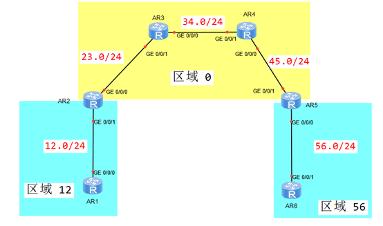
- 如图配置IP地址和OSPF区域
- 区域12启用密文的链路认证,密码为HCIE
- 区域56启用明文的区域认证,密码为HCIP
- 区域0启用最安全区域认证,密码为 HCIA
- R3-R4使用最安全密码为:HuaWei
4.2 方案
搭建实验环境,如图-4所示。
 图-4
图-4
4.3 步骤
实现此案例需要按照如下步骤进行。
1)配置IP地址和OSPF网络
- <Huawei>undo terminal monitor
- <Huawei>system–view
- [Huawei]sysname R1
- [R1]interface GigabitEthernet 0/0/0
- [R1–GigabitEthernet0/0/0]ip add 192.168.12.1 24
- [R1–GigabitEthernet0/0/0]quit
- [R1]ospf 1 router–id 1.1.1.1
- [R1–ospf-1]area 12
- [R1–ospf-1–area-0.0.0.12]network 192.168.12.0 0.0.0.255
- [R1–ospf-1–area-0.0.0.12]quit
- <Huawei>undo terminal monitor
- <Huawei>system–view
- [Huawei]sysname R2
- [R2]interface GigabitEthernet 0/0/1
- [R2–GigabitEthernet0/0/1]ip add 192.168.12.2 24
- [R2–GigabitEthernet0/0/1]quit
- [R2]interface GigabitEthernet 0/0/0
- [R2–GigabitEthernet0/0/0]ip add 192.168.23.2 24
- [R2–GigabitEthernet0/0/0]quit
- [R2]ospf 1 router–id 2.2.2.2
- [R2–ospf-1]area 12
- [R2–ospf-1–area-0.0.0.12]network 192.168.12.0 0.0.0.255
- [R2–ospf-1–area-0.0.0.12]quit
- [R2–ospf-1]area 0
- [R2–ospf-1–area-0.0.0.0]network 192.168.23.0 0.0.0.255
- [R2–ospf-1–area-0.0.0.0]quit
- <Huawei>undo terminal monitor
- <Huawei>system–view
- [Huawei]sysname R3
- [R3]interface GigabitEthernet 0/0/1
- [R3–GigabitEthernet0/0/1]ip add 192.168.23.3 24
- [R3–GigabitEthernet0/0/1]quit
- [R3]interface GigabitEthernet 0/0/0
- [R3–GigabitEthernet0/0/0]ip add 192.168.34.3 24
- [R3–GigabitEthernet0/0/0]quit
- [R3]ospf 1 router–id 3.3.3.3
- [R3–ospf-1]area 0
- [R3–ospf-1–area-0.0.0.0]network 192.168.23.0 0.0.0.255
- [R3–ospf-1–area-0.0.0.0]network 192.168.34.0 0.0.0.255
- [R3–ospf-1–area-0.0.0.0]quit
- <Huawei>undo terminal monitor
- <Huawei>system–view
- [Huawei]sysname R4
- [R4]interface GigabitEthernet 0/0/1
- [R4–GigabitEthernet0/0/1]ip add 192.168.34.4 24
- [R4–GigabitEthernet0/0/1]quit
- [R4]interface GigabitEthernet 0/0/0
- [R4–GigabitEthernet0/0/0]ip add 192.168.45.4 24
- [R4–GigabitEthernet0/0/0]quit
- [R4]ospf 1 router–id 4.4.4.4
- [R4–ospf-1]area 0
- [R4–ospf-1–area-0.0.0.0]network 192.168.34.0 0.0.0.255
- [R4–ospf-1–area-0.0.0.0]network 192.168.45.0 0.0.0.255
- [R4–ospf-1–area-0.0.0.0]quit
- <Huawei>undo terminal monitor
- <Huawei>system–view
- [Huawei]sysname R5
- [R5]interface GigabitEthernet 0/0/1
- [R5–GigabitEthernet0/0/1]ip add 192.168.45.5 24
- [R5–GigabitEthernet0/0/1]quit
- [R5]interface GigabitEthernet 0/0/0
- [R5–GigabitEthernet0/0/0]ip add 192.168.56.5 24
- [R5–GigabitEthernet0/0/0]quit
- [R5]ospf 1 router–id 5.5.5.5
- [R5–ospf-1]area 56
- [R5–ospf-1–area-0.0.0.56]network 192.168.56.0 0.0.0.255
- [R5–ospf-1–area-0.0.0.56]quit
- [R5–ospf-1]area 0
- [R5–ospf-1–area-0.0.0.0]network 192.168.45.0 0.0.0.255
- [R5–ospf-1–area-0.0.0.0]quit
- <Huawei>undo terminal monitor
- <Huawei>system–view
- [Huawei]sysname R6
- [R6]interface GigabitEthernet 0/0/1
- [R6–GigabitEthernet0/0/1]ip add 192.168.56.6 24
- [R6–GigabitEthernet0/0/1]quit
- [R6]ospf 1 router–id 6.6.6.6
- [R6–ospf-1]area 56
- [R6–ospf-1–area-0.0.0.56]network 192.168.56.0 0.0.0.255
- [R6–ospf-1–area-0.0.0.56]quit
2)配置区域12的认证
- [R1]interface GigabitEthernet 0/0/0
- [R1–GigabitEthernet0/0/0]ospf authentication–mode md5 1 cipher HCIE
- [R2]interface GigabitEthernet 0/0/1
- [R2–GigabitEthernet0/0/1]ospf authentication–mode md5 1 cipher HCIE
3)配置区域56的认证
- [R5]ospf 1
- [R5–ospf-1]area 56
- [R5–ospf-1–area-0.0.0.56]authentication–mode simple cipher HCIP
- [R6]ospf 1
- [R6–ospf-1]area 56
- [R6–ospf-1–area-0.0.0.56]authentication–mode simple cipher HCIP
4)配置区域0的认证
- [R2]ospf 1
- [R2–ospf-1]area 0
- [R2–ospf-1–area-0.0.0.0]authentication–mode md5 1 cipher HCIA
- [R3]ospf 1
- [R3–ospf-1]area 0
- [R3–ospf-1–area-0.0.0.0]authentication–mode md5 1 cipher HCIA
- [R4]ospf 1
- [R4–ospf-1]area 0
- [R4–ospf-1–area-0.0.0.0]authentication–mode md5 1 cipher HCIA
- [R5]ospf 1
- [R5–ospf-1]area 0
- [R5–ospf-1–area-0.0.0.0]authentication–mode md5 1 cipher HCIA
5)配置R3-R4之间的认证
- [R3]interface GigabitEthernet 0/0/0
- [R3–GigabitEthernet0/0/0]ospf authentication–mode md5 1 cipher HuaWei
- [R4]interface GigabitEthernet 0/0/1
- [R4–GigabitEthernet0/0/1]ospf authentication–mode md5 1 cipher HuaWei
5 案例:IPv6 基本配置
5.1 问题
- 如图配置IPv6地址
- 查看并测试IPv6接口和连通性
- 确保 PC-1 和 PC-2 互通
5.2 方案
搭建实验环境,如图-5所示。
 图-5
图-5
5.3 步骤
实现此案例需要按照如下步骤进行。
1)配置终端设备
- PC-1:
- 2001:11::1
- 64
- 2001:11::254
- PC-2:
- 2001:22::1
- 64
- 2001:22::254
2)配置网络设备
- <Huawei>undo terminal monitor
- <Huawei>system–view
- [Huawei]sysname R1
- [R1]ipv6
- [R1]interface GigabitEthernet 0/0/0
- [R1–GigabitEthernet0/0/0]ipv6 enable
- [R1–GigabitEthernet0/0/0]ipv6 address 2001:12::1 64
- [R1–GigabitEthernet0/0/0]quit
- [R1]interface GigabitEthernet 0/0/2
- [R1–GigabitEthernet0/0/2]ipv6 enable
- [R1–GigabitEthernet0/0/2]ipv6 address 2001:11::254 64
- [R1–GigabitEthernet0/0/2]quit
- <Huawei>undo terminal monitor
- <Huawei>system–view
- [Huawei]sysname R2
- [R2]ipv6
- [R2]interface GigabitEthernet 0/0/01
- [R2–GigabitEthernet0/0/1]ipv6 enable
- [R2–GigabitEthernet0/0/1]ipv6 address 2001:12::2 64
- [R2–GigabitEthernet0/0/1]quit
- [R2]interface GigabitEthernet 0/0/0
- [R2–GigabitEthernet0/0/0]ipv6 enable
- [R2–GigabitEthernet0/0/0]ipv6 address 2001:23::2 64
- [R2–GigabitEthernet0/0/0]quit
- <Huawei>undo terminal monitor
- <Huawei>system–view
- [Huawei]sysname R3
- [R3]ipv6
- [R3]interface GigabitEthernet 0/0/0
- [R3–GigabitEthernet0/0/0]ipv6 enable
- [R3–GigabitEthernet0/0/0]ipv6 address 2001:23::3 64
- [R3–GigabitEthernet0/0/0]quit
- [R3]interface GigabitEthernet 0/0/2
- [R3–GigabitEthernet0/0/2]ipv6 enable
- [R3–GigabitEthernet0/0/2]ipv6 address 2001:22::254 64
- [R3–GigabitEthernet0/0/2]quit
3)配置IPv6路由条目
- [R1]ipv6 route–static :: 0 2001:12::2
- [R3]ipv6 route–static :: 0 2001:23::2
- [R2] ipv6 route–static 2001:11:: 64 2001:12::1
- [R2] ipv6 route–static 2001:22:: 64 2001:23::3
4)测试 PC-1 与 PC2 的连通性
- PC-1>ping 2001:22::1
- Ping 2001:22::1: 32 data bytes, Press Ctrl_C to break
- From 2001:22::1: bytes=32 seq=1 hop limit=254 time<1 ms
- From 2001:22::1: bytes=32 seq=2 hop limit=254 time=15 ms
- From 2001:22::1: bytes=32 seq=3 hop limit=254 time=16 ms
- From 2001:22::1: bytes=32 seq=4 hop limit=254 time=15 ms
- From 2001:22::1: bytes=32 seq=5 hop limit=254 time=16 ms
- — 2001:22::1 ping statistics —
- 5 packet(s) transmitted
- 5 packet(s) received
- 0.00% packet loss
- round–trip min/avg/max = 0/12/16 ms
- PC-2>ping 2001:11::1
- Ping 2001:11::1: 32 data bytes, Press Ctrl_C to break
- From 2001:11::1: bytes=32 seq=1 hop limit=254 time=16 ms
- From 2001:11::1: bytes=32 seq=2 hop limit=254 time=16 ms
- From 2001:11::1: bytes=32 seq=3 hop limit=254 time=15 ms
- From 2001:11::1: bytes=32 seq=4 hop limit=254 time=16 ms
- From 2001:11::1: bytes=32 seq=5 hop limit=254 time=15 ms
- — 2001:11::1 ping statistics —
- 5 packet(s) transmitted
- 5 packet(s) received
- 0.00% packet loss
- round–trip min/avg/max = 15/15/16 ms
6 案例:配置 OSPFv3 网络
6.1 问题
- 如图配置IPv6地址和OSPFv3区域
- 查看OSPFv3邻居和数据库LSA
- 确保 R1 和 R3 可以互相访问
6.2 方案
搭建实验环境,如图-6所示。
 图-6
图-6
6.3 步骤
实现此案例需要按照如下步骤进行。
1)配置R1 地址,并启用 OSPFv3
- <Huawei>undo terminal monitor
- <Huawei>system–view
- [Huawei]sysname R1
- [R1]ipv6
- [R1]interface GigabitEthernet 0/0/0
- [R1–GigabitEthernet0/0/0]ipv6 enable
- [R1–GigabitEthernet0/0/0]ipv6 address 2001:12::1 64
- [R1–GigabitEthernet0/0/0]quit
- [R1]ospfv3 1
- [R1–ospfv3-1]router–id 1.1.1.1
- [R1–ospfv3-1]quit
- [R1]interface GigabitEthernet 0/0/0
- [R1–GigabitEthernet0/0/0]ospfv3 1 area 0
- [R1–GigabitEthernet0/0/0]quit
2)配置R2 地址,并启用 OSPFv3
- <Huawei>undo terminal monitor
- <Huawei>system–view
- [Huawei]sysname R2
- [R2]ipv6
- [R2]interface GigabitEthernet 0/0/0
- [R2–GigabitEthernet0/0/0]ipv6 enable
- [R2–GigabitEthernet0/0/0]ipv6 address 2001:23::2 64
- [R2–GigabitEthernet0/0/0]quit
- [R2]interface GigabitEthernet 0/0/1
- [R2–GigabitEthernet0/0/1]ipv6 enable
- [R2–GigabitEthernet0/0/1]ipv6 address 2001:12::2 64
- [R2–GigabitEthernet0/0/1]quit
- [R2]ospfv3 1
- [R2–ospfv3-1]router–id 2.2.2.2
- [R2–ospfv3-1]quit
- [R2]interface GigabitEthernet 0/0/1
- [R2–GigabitEthernet0/0/1]ospfv3 1 area 0
- [R2–GigabitEthernet0/0/1]quit
- [R2]interface GigabitEthernet 0/0/0
- [R2–GigabitEthernet0/0/0]ospfv3 1 area 1
- [R2–GigabitEthernet0/0/0]quit
3)配置R3 地址,并启用 OSPFv3
- <Huawei>undo terminal monitor
- <Huawei>system–view
- [Huawei]sysname R3
- [R3]ipv6
- [R3]interface GigabitEthernet 0/0/1
- [R3–GigabitEthernet0/0/1]ipv6 enable
- [R3–GigabitEthernet0/0/1]ipv6 address 2001:23::3 64
- [R3–GigabitEthernet0/0/1]quit
- [R3]ospfv3 1
- [R3–ospfv3-1]router–id 3.3.3.3
- [R3–ospfv3-1]quit
- [R3]interface GigabitEthernet 0/0/1
- [R3–GigabitEthernet0/0/1]ospfv3 1 area 1
- [R3–GigabitEthernet0/0/1]quit
4)验证PC-1与PC-2之间的互通性
- [R1]ping ipv6 2001:23::3
- PING 2001:23::3 : 56 data bytes, press CTRL_C to break
- Reply from 2001:23::3
- bytes=56 Sequence=1 hop limit=63 time = 30 ms
- Reply from 2001:23::3
- bytes=56 Sequence=2 hop limit=63 time = 30 ms
- Reply from 2001:23::3
- bytes=56 Sequence=3 hop limit=63 time = 40 ms
- Reply from 2001:23::3
- bytes=56 Sequence=4 hop limit=63 time = 30 ms
- Reply from 2001:23::3
- bytes=56 Sequence=5 hop limit=63 time = 30 ms
- — 2001:23::3 ping statistics —
- 5 packet(s) transmitted
- 5 packet(s) received
- 0.00% packet loss
- round–trip min/avg/max = 30/32/40 ms [/hidecontent]

