1 案例:基于全局模式的DHCP
1.1 需求
- 在路由器上配置基于全局模式的DHCP
- DHCP的地址池为 192.168.1.0/24
- DHCP的网关地址为 192.168.1.254
- DHCP的DNS 为 8.8.8.8
- DHCP的租期 为 3天
1.2 方案
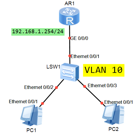
使用eNSP搭建实验环境,如图-1所示。
 图-1
图-1
1.3 步骤
实现此案例需要按照如下步骤进行。[hidecontent type=”payshow”]
1)配置PC1/2获得IP地址的方式为“自动获取/DHCP”
2)配置 SW1,确保DHCP客户端与DHCP服务器互通
- <Huawei>undo ter
- <Huawei>undo terminal mo
- <Huawei>undo terminal monitor
- [Huawei]sysname SW1
- [SW1]vlan 10
- [SW1–vlan10]quit
- [SW1]interface Ethernet0/0/1
- [SW1–Ethernet0/0/1]port link access
- [SW1–Ethernet0/0/1]port default vlan 10
- [SW1–Ethernet0/0/1]quit
- [SW1]interface Ethernet0/0/2
- [SW1–Ethernet0/0/2]port link access
- [SW1–Ethernet0/0/2]port default vlan 10
- [SW1–Ethernet0/0/2]quit
- [SW1]interface Ethernet0/0/3
- [SW1–Ethernet0/0/3]port link access
- [SW1–Ethernet0/0/3]port default vlan 10
- [SW1–Ethernet0/0/3]quit
3)配置R1,将其配置为 DHCP 服务器
- <Huawei>undo terminal monitor
- <Huawei>system–view
- [Huawei]sysname R1
- [R1]interface GigabitEthernet 0/0/0
- [R1–GigabitEthernet0/0/0]ip address 192.168.1.254 24
- [R1–GigabitEthernet0/0/0]quit
- [R1]dhcp enable
- [R1]ip pool DHCP
- [R1–ip–pool–DHCP]network 192.168.1.0 mask 24
- [R1–ip–pool–DHCP]gateway–list 192.168.1.254
- [R1–ip–pool–DHCP]dns–list 8.8.8.8
- [R1–ip–pool–DHCP]lease day 3
- [R1–ip–pool–DHCP]quit
- [R1]interface GigabitEthernet 0/0/0
- [R1–GigabitEthernet0/0/0]dhcp select global
- [R1–GigabitEthernet0/0/0]quit
4)验证 PC1/2 获得IP地址
2 案例:配置DHCP中继
2.1 需求
- 配置DHCP中继,让客户端从DHCP服务器获取地址
- 客户机可以ping通R1
2.2 方案
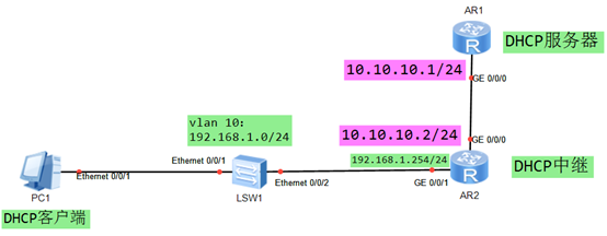
使用eNSP搭建实验环境,如图-2所示。
 图-2
图-2
2.3 步骤
实现此案例需要按照如下步骤进行。
1)配置PC1为DHCP客户端
2)配置 SW1 确保 PC1与 R2(PC1的网关)互通
- <Huawei>undo terminal monitor
- <Huawei>system–view
- [Huawei]sysname SW1
- [SW1]vlan 10
- [SW1–vlan10]quit
- [SW1]interface eth0/0/1
- [SW1–Ethernet0/0/1]port link access
- [SW1–Ethernet0/0/1]port default vlan 10
- [SW1–Ethernet0/0/1]quit
- [SW1]interface eth0/0/2
- [SW1–Ethernet0/0/2]port link access
- [SW1–Ethernet0/0/2]port default vlan 10
- [SW1–Ethernet0/0/2]quit
3)配置DHCP中继(R2)
- <Huawei>undo terminal monitor
- <Huawei>system–view
- [Huawei]sysname R2
- [R2]interface gi0/0/1
- [R2–GigabitEthernet0/0/1]ip address 192.168.1.254 24
- [R2–GigabitEthernet0/0/1]quit
- [R2]interface gi0/0/0
- [R2–GigabitEthernet0/0/0]ip address 10.10.10.2 24
- [R2–GigabitEthernet0/0/0]quit
- [R2]dhcp enable
- [R2]interface gi0/0/01
- [R2–GigabitEthernet0/0/1]dhcp select relay
- [R2–GigabitEthernet0/0/1]dhcp relay server–ip 10.10.10.1
- [R2–GigabitEthernet0/0/1]quit
4)配置DHCP服务器(R1)
- <Huawei>undo terminal monitor
- <Huawei>system–view
- [Huawei]sysname R1
- [R1]interface GigabitEthernet 0/0/0
- [R1–GigabitEthernet0/0/0]ip address 10.10.10.1 24
- [R1–GigabitEthernet0/0/0]quit
- [R1]dhcp enable
- [R1]ip pool DHCP
- [R1–ip–pool–DHCP]network 192.168.1.0 mask 24
- [R1–ip–pool–DHCP]gateway–list 192.168.1.254
- [R1–ip–pool–DHCP]dns–list 8.8.8.8
- [R1–ip–pool–DHCP]quit
- [R1]interface GigabitEthernet 0/0/0
- [R1–GigabitEthernet0/0/0]dhcp select global
- [R1–GigabitEthernet0/0/0]quit
- [R1]ip route–static 192.168.1.0 24 10.10.10.2
5)验证主机自动获取的IP地址
3 案例:交换机配置DHCP服务器
3.1 需求
- 配置两个地址池:192.168.1.0/24和192.168.2.0/24
- 配置两个VLAN:VLAN 10和VLAN 20
- 将四台主机分别加入VLAN
- 自动获取IP地址,确保全网互通
3.2 方案
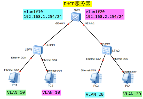
使用eNSP搭建实验环境,如图-3所示。
 图-3
图-3
3.3 步骤
实现此案例需要按照如下步骤进行。
1)配置DHCP客户端
2)配置DHCP客户端与DHCP服务器之间的传输网络(SW1/2/3)
- <Huawei>undo terminal monitor
- <Huawei>system–view
- [Huawei]sysname SW1
- [SW1]vlan batch 10 20
- [SW1]interface eth0/0/1
- [SW1–Ethernet0/0/1]port link access
- [SW1–Ethernet0/0/1]port default vlan 10
- [SW1–Ethernet0/0/1]quit
- [SW1]interface eth0/0/2
- [SW1–Ethernet0/0/2]port link access
- [SW1–Ethernet0/0/2]port default vlan 10
- [SW1–Ethernet0/0/2]quit
- [SW1]interface GigabitEthernet 0/0/1
- [SW1–GigabitEthernet0/0/1]port link trunk
- [SW1–GigabitEthernet0/0/1]port trunk allow–pass vlan all
- [SW1–GigabitEthernet0/0/1]quit
- <Huawei>undo terminal monitor
- <Huawei>system–view
- [Huawei]sysname SW2
- [SW2]vlan batch 10 20
- [SW2]interface eth0/0/1
- [SW2–Ethernet0/0/1]port link access
- [SW2–Ethernet0/0/1]port default vlan 20
- [SW2–Ethernet0/0/1]quit
- [SW2]interface eth0/0/2
- [SW2–Ethernet0/0/2]port link access
- [SW2–Ethernet0/0/2]port default vlan 20
- [SW2–Ethernet0/0/2]quit
- [SW2]interface GigabitEthernet 0/0/2
- [SW2–GigabitEthernet0/0/2]port link trunk
- [SW2–GigabitEthernet0/0/2]port trunk allow–pass vlan all
- [SW2–GigabitEthernet0/0/2]quit
- <Huawei>undo terminal monitor
- <Huawei>system–view
- [Huawei]sysname SW3
- [SW3]vlan batch 10 20
- [SW3]interface GigabitEthernet 0/0/1
- [SW3–GigabitEthernet0/0/1]port link trunk
- [SW3–GigabitEthernet0/0/1]port trunk allow–pass vlan all
- [SW3–GigabitEthernet0/0/1]quit
- [SW3]interface GigabitEthernet 0/0/2
- [SW3–GigabitEthernet0/0/2]port link trunk
- [SW3–GigabitEthernet0/0/2]port trunk allow–pass vlan all
- [SW3–GigabitEthernet0/0/2]quit
3)配置DHCP服务器
- <Huawei>undo terminal monitor
- <Huawei>system–view
- [Huawei]sysname SW3
- [SW3]vlan 10
- [SW3–vlan10]quit
- [SW3]vlan 20
- [SW3–vlan20]quit
- [SW3]interface Vlanif 10
- [SW3–Vlanif10]ip address 192.168.1.254 24
- [SW3–Vlanif10]quit
- [SW3]interface Vlanif 20
- [SW3–Vlanif20]ip address 192.168.2.254 24
- [SW3–Vlanif20]quit
- [SW3]dhcp enable
- [SW3]ip pool VLAN10
- [SW3–ip–pool–vlan10]network 192.168.1.0 mask 24
- [SW3–ip–pool–vlan10]gateway–list 192.168.1.254
- [SW3–ip–pool–vlan10]dns–list 8.8.8.8
- [SW3–ip–pool–vlan10]quit
- [SW3]ip pool VLAN20
- [SW3–ip–pool–vlan20]network 192.168.2.0 mask 24
- [SW3–ip–pool–vlan20]gateway–list 192.168.2.254
- [SW3–ip–pool–vlan20]dns–list 8.8.8.8
- [SW3–ip–pool–vlan20]quit
- [SW3]interface vlanif 10
- [SW3–Vlanif10]dhcp select global
- [SW3–Vlanif10]quit
- [SW3]interface Vlanif 20
- [SW3–Vlanif20]dhcp select global
- [SW3–Vlanif20]quit
4)验证
四台主机可以获得IP地址,并可以互相ping通。
4 案例:DHCP综合实战
4.1 需求
- 如图配置设备的IP地址,确保设备之间可以互通
- PC1/2的网关位于 SW1,PC4/5的网关位于R2,PC3的网关位于R1
- 确保PC获得正确的IP地址,实现PC之间的互通
4.2 方案
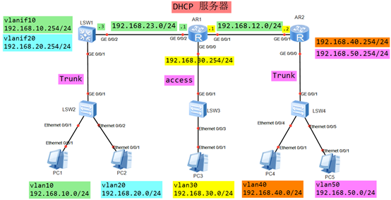
使用eNSP搭建实验环境,如图-4所示。
 图-4
图-4
4.3 步骤
实现此案例需要按照如下步骤进行。
1)配置PC1/2/3/4/5为 DHCP客户端
2)配置DHCP客户端与网关设备之间的传输网络-SW2/3/4
- <Huawei>undo terminal monitor
- <Huawei>system–view
- [Huawei]sysname SW2
- [SW2]vlan batch 10 20
- [SW2]interface eth0/0/1
- [SW2–Ethernet0/0/1]port link access
- [SW2–Ethernet0/0/1]port default vlan 10
- [SW2–Ethernet0/0/1]quit
- [SW2]interface Ethernet0/0/2
- [SW2–Ethernet0/0/2]port link access
- [SW2–Ethernet0/0/2]port default vlan 20
- [SW2–Ethernet0/0/2]quit
- [SW2]interface GigabitEthernet 0/0/1
- [SW2–GigabitEthernet0/0/1]port trunk allow–pass vlan all
- [SW2–GigabitEthernet0/0/1]quit
- [SW2]
- <Huawei>undo terminal monitor
- <Huawei>system–view
- [Huawei]sysname SW3
- [SW3]vlan 30
- [SW3–vlan30]quit
- [SW3]interface eth0/0/3
- [SW3–Ethernet0/0/3]port link access
- [SW3–Ethernet0/0/3]port default vlan 30
- [SW3–Ethernet0/0/3]quit
- [SW3]interface GigabitEthernet 0/0/1
- [SW3–GigabitEthernet0/0/1]port link access
- [SW3–GigabitEthernet0/0/1]port default vlan 30
- [SW3–GigabitEthernet0/0/1]quit
- [SW3]
- <Huawei>undo terminal monitor
- <Huawei>system–view
- [Huawei]sysname SW4
- [SW4]vlan batch 40 50
- [SW4]interface Ethernet0/0/4
- [SW4–Ethernet0/0/4]port link access
- [SW4–Ethernet0/0/4]port default vlan 40
- [SW4–Ethernet0/0/4]quit
- [SW4]interface Ethernet0/0/5
- [SW4–Ethernet0/0/5]port link access
- [SW4–Ethernet0/0/5]port default vlan 50
- [SW4–Ethernet0/0/5]quit
- [SW4]interface GigabitEthernet 0/0/1
- [SW4–GigabitEthernet0/0/1]port link trunk
- [SW4–GigabitEthernet0/0/1]port trunk allow–pass vlan all
- [SW4–GigabitEthernet0/0/1]quit
3)配置 DHCP 客户端的网关
- <Huawei>undo terminal monitor
- <Huawei>system–view
- [Huawei]sysname SW1
- [SW1]vlan batch 10 20
- [SW1]interface GigabitEthernet 0/0/1
- [SW1–GigabitEthernet0/0/1]port link trunk
- [SW1–GigabitEthernet0/0/1]port trunk allow–pass vlan all
- [SW1–GigabitEthernet0/0/1]quit
- [SW1]vlan 23
- [SW1–vlan23]quit
- [SW1]interface gi0/0/2
- [SW1–GigabitEthernet0/0/2]port link access
- [SW1–GigabitEthernet0/0/2]port default vlan 23
- [SW1–GigabitEthernet0/0/2]quit
- [SW1]interface Vlanif 10
- [SW1–Vlanif10]ip address 192.168.10.254 24
- [SW1–Vlanif10]quit
- [SW1]interface Vlanif 20
- [SW1–Vlanif20]ip address 192.168.30.254 24
- [SW1–Vlanif20]quit
- [SW1]interface Vlanif 23
- [SW1–Vlanif23]ip address 192.168.23.3 24
- [SW1–Vlanif23]quit
- <Huawei>undo terminal monitor
- <Huawei>system–view
- [Huawei]sysname R1
- [R1]interface GigabitEthernet 0/0/0
- [R1–GigabitEthernet0/0/0]ip address 192.168.30.254 24
- [R1–GigabitEthernet0/0/0]quit
- [R1]interface GigabitEthernet 0/0/1
- [R1–GigabitEthernet0/0/1]ip address 192.168.12.1 24
- [R1–GigabitEthernet0/0/1]quit
- [R1]interface GigabitEthernet 0/0/2
- [R1–GigabitEthernet0/0/2]ip address 192.168.23.1 24
- [R1–GigabitEthernet0/0/2]quit
- <Huawei>undo terminal monitor
- <Huawei>system–view
- [Huawei]sysname R2
- [R2]interface GigabitEthernet 0/0/1
- [R2–GigabitEthernet0/0/1]ip address 192.168.12.2 24
- [R2–GigabitEthernet0/0/1]quit
- [R2]interface GigabitEthernet 0/0/0.4
- [R2–GigabitEthernet0/0/0.4]dot1q termination vid 40
- [R2–GigabitEthernet0/0/0.4]arp broadcast enable
- [R2–GigabitEthernet0/0/0.4]ip address 192.168.40.254 24
- [R2–GigabitEthernet0/0/0.4]quit
- [R2]interface GigabitEthernet 0/0/0.5
- [R2–GigabitEthernet0/0/0.5]dot1q termination vid 50
- [R2–GigabitEthernet0/0/0.5]arp broadcast enable
- [R2–GigabitEthernet0/0/0.5]ip address 192.168.50.254 24
- [R2–GigabitEthernet0/0/0.5]quit
4)配置 DHCP 服务器
- [R1]dhcp enable
- [R1]ip pool VLAN10
- [R1–ip–pool–VLAN10]network 192.168.10.0 mask 24
- [R1–ip–pool–VLAN10]gateway–list 192.168.10.254
- [R1–ip–pool–VLAN10]quit
- [R1]ip pool VLAN20
- [R1–ip–pool–VLAN20]network 192.168.20.0 mask 24
- [R1–ip–pool–VLAN20]gateway–list 192.168.20.254
- [R1–ip–pool–VLAN20]quit
- [R1]ip pool VLAN30
- [R1–ip–pool–VLAN30]network 192.168.30.0 mask 24
- [R1–ip–pool–VLAN30]gateway–list 192.168.30.254
- [R1–ip–pool–VLAN30]quit
- [R1]ip pool VLAN40
- [R1–ip–pool–VLAN40]network 192.168.40.0 mask 24
- [R1–ip–pool–VLAN40]gateway–list 192.168.40.254
- [R1–ip–pool–VLAN40]quit
- [R1]ip pool VLAN50
- [R1–ip–pool–VLAN50]network 192.168.50.0 mask 24
- [R1–ip–pool–VLAN50]gateway–list 192.168.50.254
- [R1–ip–pool–VLAN50]quit
- [R1]interface GigabitEthernet 0/0/0
- [R1–GigabitEthernet0/0/0]dhcp select global
- [R1–GigabitEthernet0/0/0]quit
- [R1]interface GigabitEthernet 0/0/1
- [R1–GigabitEthernet0/0/1]dhcp select global
- [R1–GigabitEthernet0/0/1]quit
- [R1]interface GigabitEthernet 0/0/2
- [R1–GigabitEthernet0/0/2]dhcp select global
- [R1–GigabitEthernet0/0/2]quit
- [R1]ip route–static 192.168.10.0 24 192.168.23.3
- [R1]ip route–static 192.168.20.0 24 192.168.23.3
- [R1]ip route–static 192.168.40.0 24 192.168.12.2
- [R1]ip route–static 192.168.50.0 24 192.168.12.2
5)配置 DHCP 中继
- [SW1]dhcp enable
- [SW1]interface Vlanif 10
- [SW1–Vlanif10]dhcp select relay
- [SW1–Vlanif10]dhcp relay server–ip 192.168.23.1
- [SW1–Vlanif10]quit
- [SW1]interface Vlanif 20
- [SW1–Vlanif20]dhcp select relay
- [SW1–Vlanif20]dhcp relay server–ip 192.168.23.1
- [SW1–Vlanif20]quit
- [SW1]ip route–static 0.0.0.0 0 192.168.23.1
- [R2]dhcp enable
- [R2]interface GigabitEthernet 0/0/0.4
- [R2–GigabitEthernet0/0/0.4]dhcp select relay
- [R2–GigabitEthernet0/0/0.4]dhcp relay server–ip 192.168.12.1
- [R2–GigabitEthernet0/0/0.4]quit
- [R2]interface GigabitEthernet 0/0/0.5
- [R2–GigabitEthernet0/0/0.5]dhcp select relay
- [R2–GigabitEthernet0/0/0.5]dhcp relay server–ip 192.168.12.1
- [R2–GigabitEthernet0/0/0.5]quit
- [R2]ip route–static 0.0.0.0 0 192.168.12.1
6)验证 DHCP 客户端获得IP地址
- [sw3]vlan 30
- [sw3]int e0/0/1
- [sw3–e0/0/1]port link–type access
- [sw3–e0/0/1]port default vlan 30
- [sw3]int 0/0/2
- [sw3–e0/0/2]port link–type trunk
- [sw3–e0/0/2]port trunk allow–pass vlan all[/hidecontent]

